
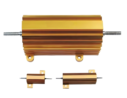
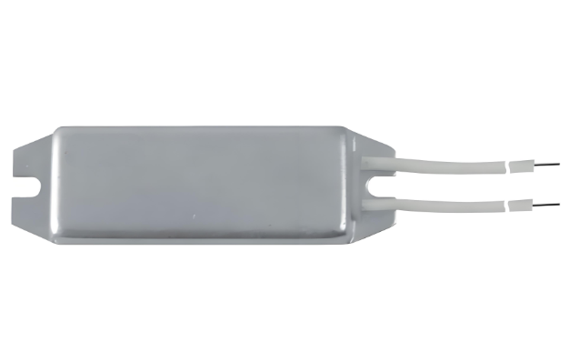
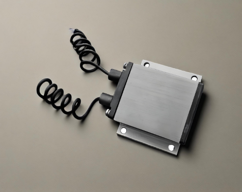
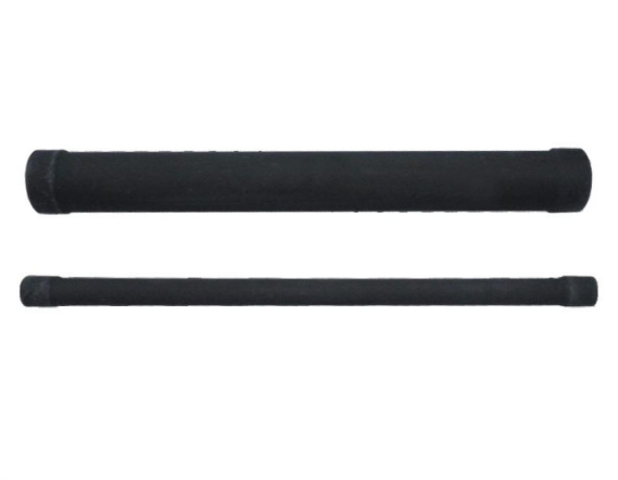
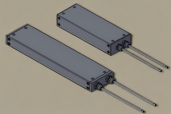
RE power aluminum case wound resistor


Characteristics
Molded construction for environmental protection
Complete welded construction
Meets applicable requirements of Mil - PRF - 18546
Available in non - inductive styles with Ayrton Perrywinding for lowest reactive components
Mounts on chassis to utilize heat - sink effect
Excellent stability in operation
Dimensions(mm)
| Type | A±0.1 | B±0.1 | C±0.2 | D±1.5 | E±0.4 | F±0.1 | G±0.4 | H±0.2 | J±0.2 | K±0.2 | L±0.1 | M±0.02 | N±0.1 | P±0.8 |
|---|---|---|---|---|---|---|---|---|---|---|---|---|---|---|
| RE605 | 11.2 | 12.5 | 15.2 | 28.6 | 8.5 | 16.4 | 8.1 | 1.7 | 3.8 | 2.4 | 1.5 | 1.3 | 6.7 | |
| RE610 | 14.2 | 15.9 | 19 | 34.9 | 10.7 | 20.3 | 9.9 | 1.9 | 4.2 | 2.4 | 2.4 | 2 | 2.2 | 8.0 |
| RE615 | 16.2 | 19.6 | 21 | 49.2 | 14 | 27.4 | 13.1 | 1.9 | 5.9 | 4.4 | 3.2 | 2 | 2.2 | 11.1 |
| RE630 | 40 | 24 | 50 | 70.6 | 16 | 29 | 15.5 | 2.2 | 6.6 | 5 | 3.2 | 2.2 | 2.2 | 10.3 |
Rated Power
RE resistor power ratings are to be mounted with the following heat sink:
RE 7.5/12.5W: 102x152x51x1mm
RE 25W: 127x178x61x1mm
RE 50W: 305x305x1.5mm
RE 75W: 305x305x1.5mm
RE 100W/250W: 305X305X3.2mm
RE 150W: 305×305×3.2mm
RE 300W: 610×610×3.2mm
Ambient Temperature vs Derating Curve
Derating is required for ambient temperatures above 25. See the following graph.
Curves A, B, C apply to operation of unmounted resistors.
Curves D applies to all types mounted with specified heat sink.
A: RE605, 610 unmounted
B: RE615 unmounted
C: RE630, 640, 650 unmounted
D: All types mounted with recommended aluminum heat sink
Reduced Heat Sink Derating Curve
(Derating is also required when recommended heat sink area is reduced.)
A: RE605, 610
B: RE615
C: RE630, 640, 650
Technical Specifications
| Type | MIL - PRF - 18546TYPE | P25°C Rated power(W) | Resistance Range | Isolation Voltage | Temperature coefficient (10⁻⁶/K) | |||
|---|---|---|---|---|---|---|---|---|
| Civil | Military | ±0.25% | ±0.5% | ±1%, ±5%, ±10% | ||||
| RE605 | RE60G | 7.5(5) | 5 | R50~1K2 | R10~1K2 | R10~3K0 | 1000V | ±20 |
| RE605N | RE60N | 7.5(5) | 5 | 1R0~200R | 1R0~800R | 1R~1K5 | ||
| RE610 | RE65G | 12.5(10) | 10 | R50~2K7 | R10~2K7 | R10~4K7 | ||
| RE610N | RE65N | 12.5(10) | 10 | 1R0~1K2 | 1R0~1K2 | 1R0~2K0 | ||
| RE615 | RE70G | 25 | 20 | R10~3K9 | R10~3K9 | R1~10K | ||
| RE615N | RE70N | 25 | 20 | 1R0~2K7 | 1R0~2K7 | 1R0~4K7 | ||
| RE630 | RE75G | 50 | 30 | R10~5K6 | R10~5K6 | R1~12K | 2000V | ±50 |
| RE630N | RE75N | 50 | 30 | 1R0~3K9 | 1R0~3K9 | 1R0~5K0 | ||
| RE640 | RE77G | 100 | 50 | R05~10K | R5~12K | R5~18K | 4500V | ±100 |
| RE640N | RE77N | 100 | 50 | R05~5K | 1R0~5K6 | 1R0~9K0 | ||
| RE650 | RE80G | 120 | 60 | R10~20K | R10~20K | R10~25K | ||
| RE650N | RE80N | 120 | 60 | 1R0~8K2 | 1R0~8K2 | 1R0~12K |
Material Specifications
Element: Copper - nickel alloy or nickel - chromium alloy depending on resistance value
Core: Ceramic, steatite, depending on physical size
Encapsulant: Silico molded materials
Housing: aluminum with hard anodic coating
End Caps: stainless steel
Standard Terminals: Tinned Copperwires on Rx24 7.5W CMEL
RE 50W Threaded stainless steel terminals in RE 100W/250W
Part Marking: VTM, Model, Wattage, Value, Tolerance, Date Code
Special Modifications
Some modifications are available on customer request. The details are as follows:
Terminal configurations and materials
Resistance values and tolerances
Low TCR
Housing configuration
Thread of mounting hole
Pre - processing and other additional testing
Applicable MIL Specifications
MIL - PRF - 18546 is the military specification Covering aluminum housed, chassis mount, power resistors.
Non - inductive resistance
Same physical and electrical characteristics as the normal one are available for non - inductive resistor. Also, they are defined by adding another letter N after the model number (RE605N, for example).
Performance
| Test Item | Specifications | Test Methods | ||
|---|---|---|---|---|
| Thermal shock | ΔR≤ ± ( 0.5%R + 0.05Ω ) | Pₙ/ - 55°C, 15min | ||
| Short time overload | ΔR≤ ± ( 0.5%R + 0.05Ω ) | √5RP, 5S | ||
| Dielectric withstanding voltage | ΔR≤ ± ( 0.2%R + 0.05Ω ) | RE605 - RE615 1000Vₐₙ | RE630 2000Vₐₙ | RE640 - RE650 4500Vₐₙₑₐ |
| Moisture proof | ΔR≤ ± ( 1.0%R + 0.05Ω ) | 40°C, RH93±3%, 240h | ||
| Shock proof | ΔR≤ ± ( 0.2%R + 0.05Ω ) | 100g, 6ms, 10cycles | ||
| Vibration with high frequency | ΔR≤ ± ( 0.2%R + 0.05Ω ) | 10~200HZ, 20g, 6h | ||
| Load life | ΔR≤ ± ( 1.0%R + 0.05Ω ) | 25°C, Pₙ, 1000h |


-
 RE power aluminum case wound resistor
-
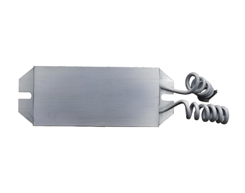
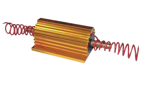
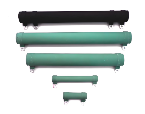
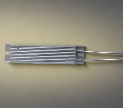 RXLG - B Power type aluminum shell wire wound resistor
-
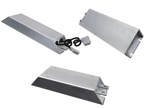
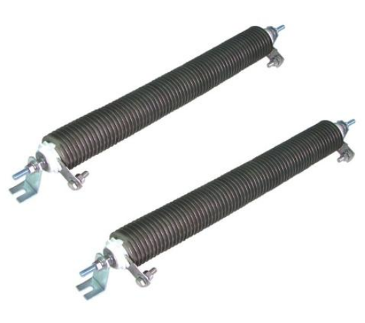
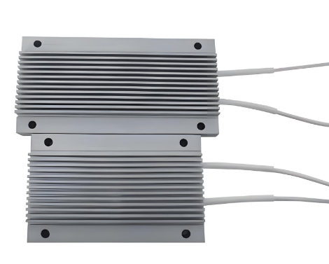 RXLB - M Power type aluminum shell wire wound resistor
-
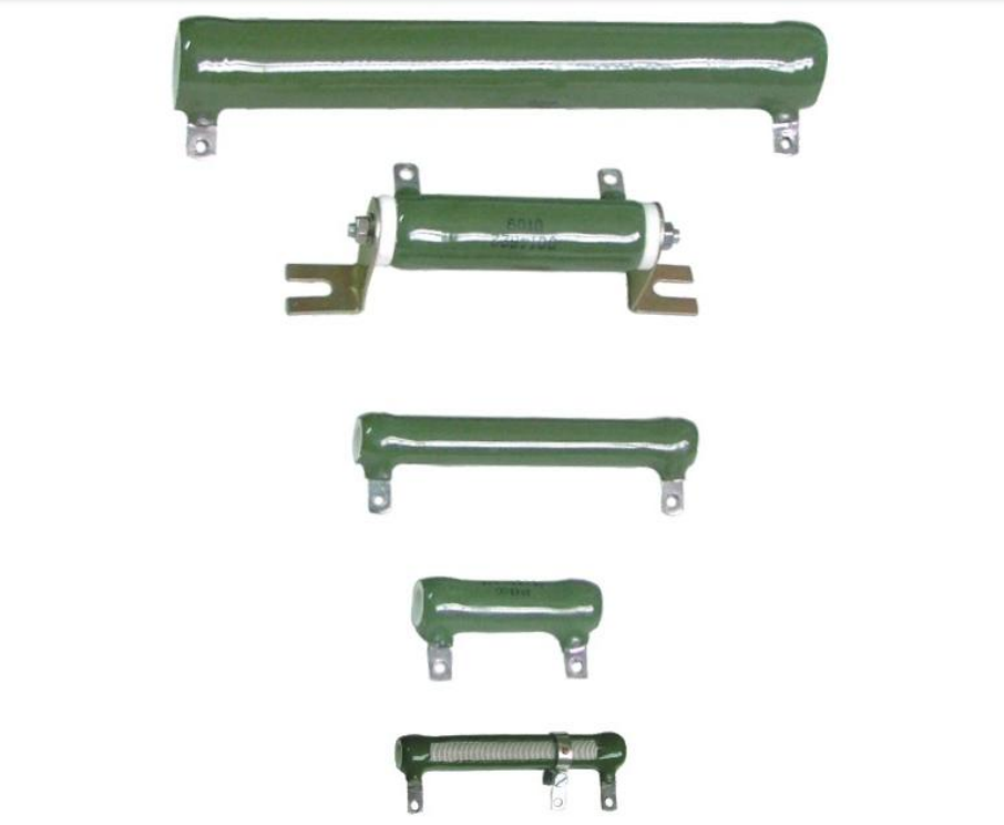
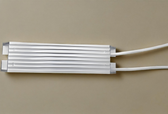 RXLG - A Power type aluminum shell wire wound resistor
-
 RXL power aluminum encased wire - wound resistors
-
 RXLB power aluminum encased wire - wound resistors
-
 RX24 aluminum encased power wire - wound resistors
-
 RXLG high power aluminum encased wire - wound resistors
-
 RXLG - A (RXG) high power aluminum alloy resistor
-
 RXLG - T High voltage withstand power aluminum alloy resistor
-
 REW600 water cooled power resistors wirewound, aluminum
-
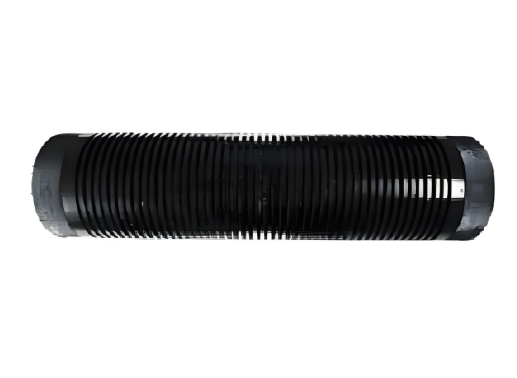
 REWR huge power circular edge wound resistors
-
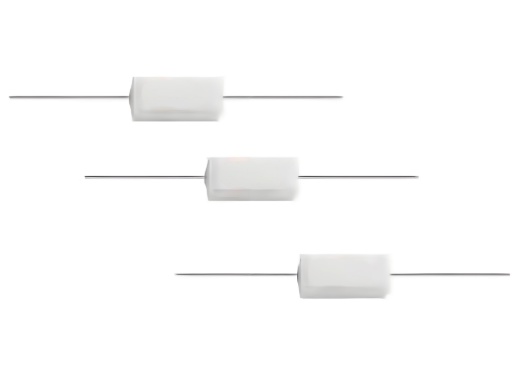 RX27 power ceramic encased wire - wound resistors
-
 RXGM high power coated wire - wound resistors
-
 RXGI high power coated wire - wound resistors
-
 RX20 high power vitreous enameled wire - wound resistors
-
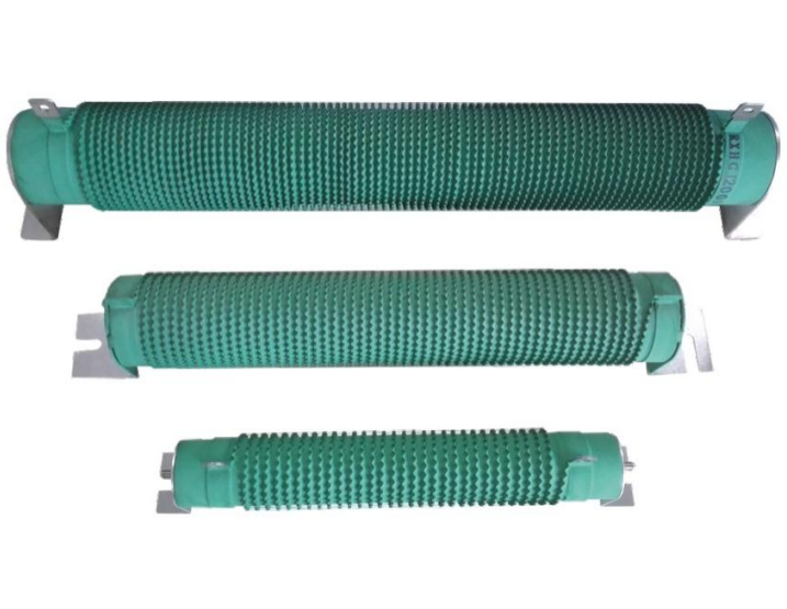 RXHGI high power wane ripple coated wire - wound resistors
-
 Aluminum Nitride Resistance
-
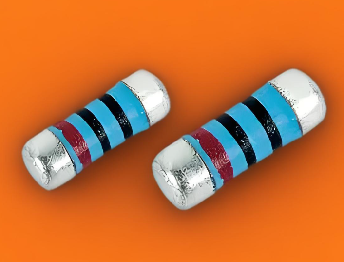
 TY Surface Mount Wire-Wound Resistor (SMR)
-
 RXLG - E High energy impact resistant aluminum shell wire
-
 Wire wound type Ignition Noise Suppression Resistor
-
 Wire wound type Ignition Noise Suppression Resistor
-
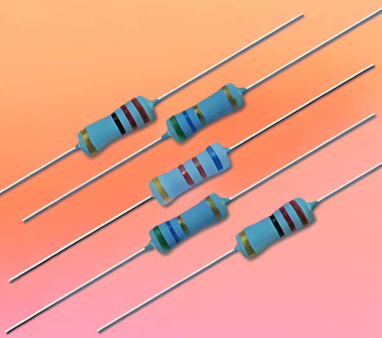
 TY Power Wirewound Resistor
-
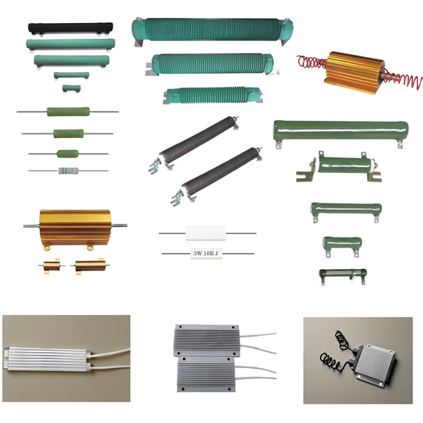
 High Power Resistor


Resistor Supplies - Jepsun Tech Corporation
+86755-29796190 +8615920026751 [email protected]
Huangjiazhongxin building Donghuan Road Longhua District SHENZHEN City, GUANGDONG Prov. CHINA 518000