How to Read Metal Film Resistor Specifications: Decoding Datasheets & Failure Analysis
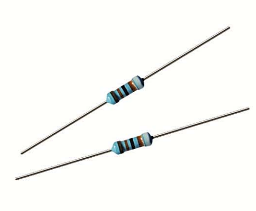
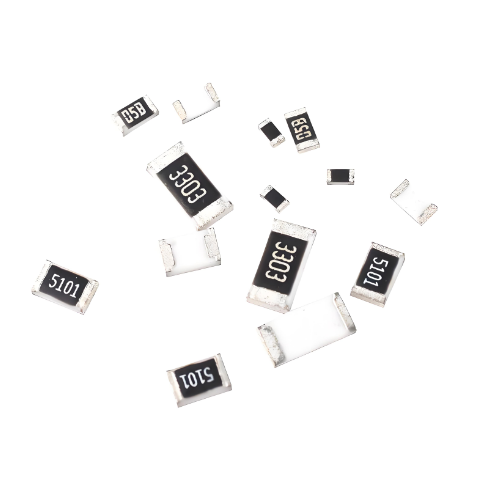
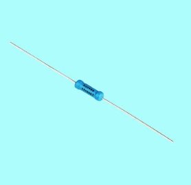
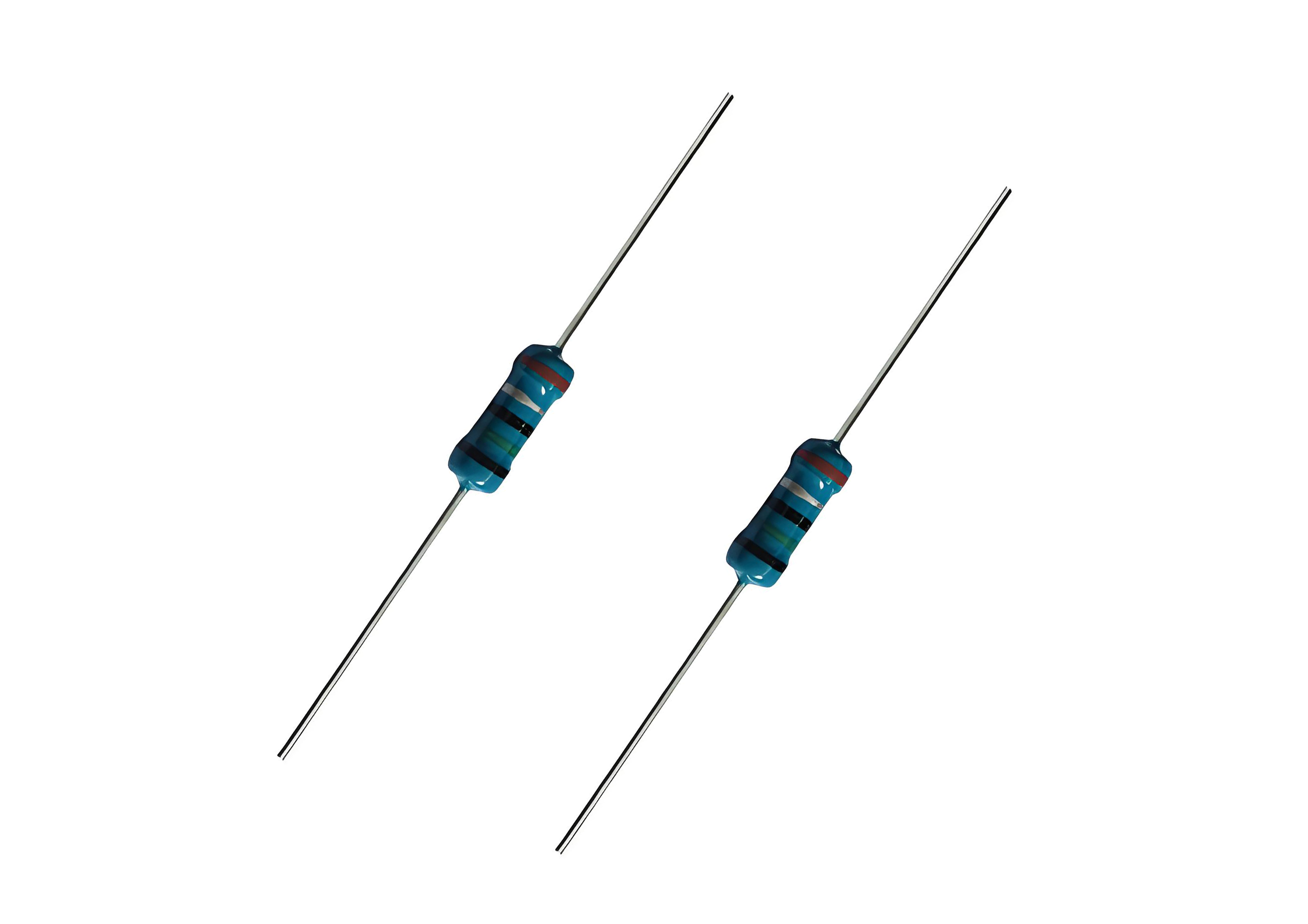
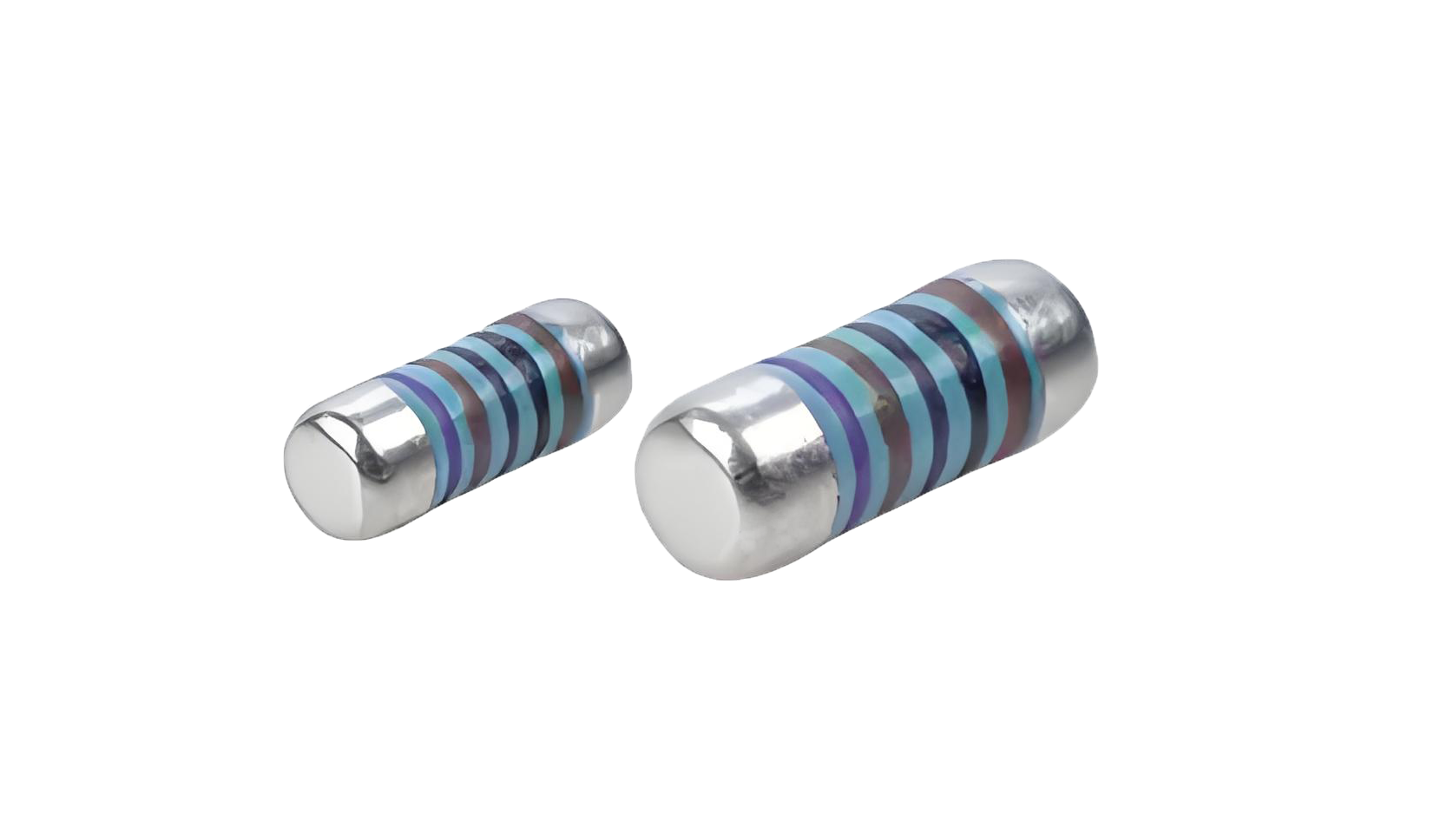
Metal film resistors are widely used in precision electronics due to their stability, low noise, and tight tolerance. However, interpreting their datasheets and diagnosing failures can be challenging. This guide breaks down key specifications, explains common failure modes, and provides actionable solutions—helping engineers, technicians, and hobbyists make informed decisions.

Key Metal Film Resistor Specifications
Understanding these critical parameters ensures proper resistor selection for your circuit:
| Specification | Typical Range | Importance |
|---|---|---|
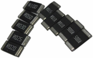
| Resistance Value (Ω) | 1Ω – 10MΩ | Core parameter for circuit design |
| Tolerance | ±0.1% – ±5% | Determines precision level |
| Temperature Coefficient (TCR) | ±15 – ±100 ppm/°C | Critical for thermal stability |
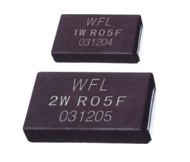
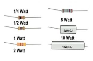
| Power Rating | 0.125W – 5W | Prevents overheating failures |
| Voltage Coefficient | <0.1%/V | Affects high-voltage applications |
Step-by-Step Datasheet Decoding
Problem: Many engineers struggle to locate critical parameters in lengthy datasheets. Here's how to efficiently extract key data:
Solution: Focus on these sections in order:
Absolute Maximum Ratings - Never exceed these values
Electrical Characteristics - Find TCR, noise, stability data
Derating Curves - Shows power reduction at high temps
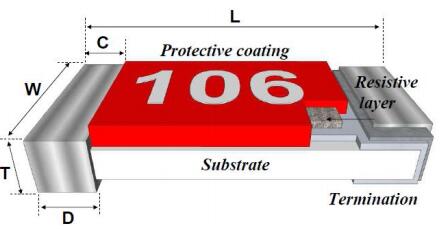
Package Dimensions - Verify mechanical fit
Reliability Data- MTBF, failure rate statistics
For high-temperature applications, pay special attention to the derating curve and TCR values, as these directly impact long-term reliability in harsh environments.
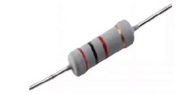
Common Failure Modes & Analysis
When metal film resistors fail, these are the most frequent causes based on field data:
| Failure Mode | Percentage of Cases | Visual Indicators |
|---|---|---|
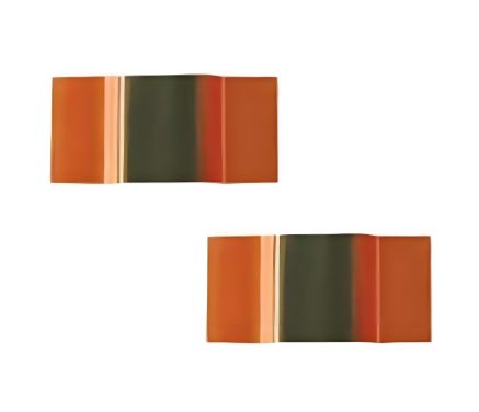
| Overheating | 42% | Discoloration, cracked coating |
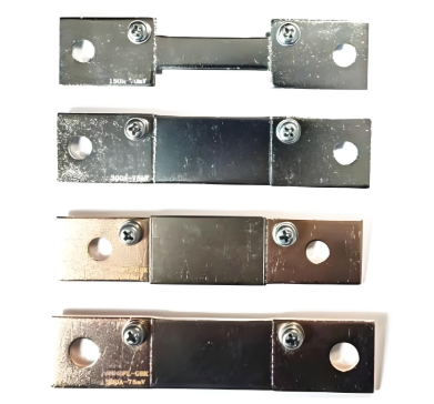
| Mechanical Damage | 28% | Bent leads, broken body |
| Corrosion | 18% | Greenish deposits on leads |
| Manufacturing Defects | 12% | Inconsistent resistance readings |
Proven Solutions for Resistor Failures
Problem: Your resistor bank shows a 15% failure rate after 6 months in a power supply application.
Solution Implementation:
| Root Cause | Corrective Action | Expected Improvement |
|---|---|---|
| Inadequate power rating | Upgrade to 1W resistors (from 0.5W) | 80% reduction in failures |
| Poor ventilation | Increase PCB spacing to 5mm | 40% lower operating temp |
| High surge currents | Add parallel TVS diodes | Eliminates surge damage |
For corrosion-prone environments, specify conformal-coated resistors or switch to sulfur-resistant versions to prevent premature failure.
How to Select the Right Metal Film Resistor
Use this decision matrix for optimal selection in different applications:
| Application | Critical Specs | Recommended Type |
|---|---|---|
| Precision instrumentation | TCR < ±25ppm/°C, ±0.1% tolerance | RJ14 series |
| Automotive electronics | AEC-Q200 compliant, 150°C rating | RJ17 automotive grade |
| High-voltage circuits | 500V rating, low voltage coefficient | RJ18 HV series |
| Cost-sensitive consumer | ±5% tolerance, standard TCR | RJ15 economy line |
Remember that derating power specifications by at least 30% significantly improves reliability in most applications.
Mastering Resistor Specifications
By systematically analyzing datasheets, understanding failure mechanisms, and applying targeted solutions, you can significantly improve circuit reliability. Always verify critical parameters like TCR and power derating for your specific operating conditions, and consider environmental factors that may affect long-term performance.