Title: High Frequency Non-Inductive Resistors for RF, Microwave, and Power Electronics – Selection Guide & Applications
Introduction
This High Frequency Non-Inductive Resistors for RF, Microwave, and Power Electronics – Selection Guide & Applications explains why non-inductive resistor choices are critical when working at GHz frequencies and in precision power electronics. At high frequency, even tiny parasitic inductance turns a resistor into a reactive element, upsetting matching networks, creating loss, or causing unwanted resonances. Use this guide to quickly identify the right resistor technology, key datasheet parameters, numeric examples, and practical remedies for the most common field problem you’ll face.

Table of Contents
Why Non-Inductive Resistors Matter
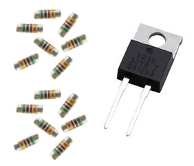
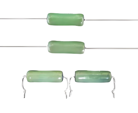
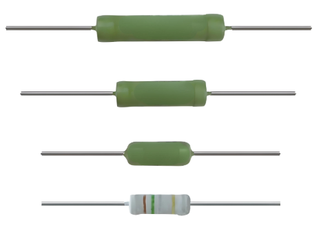
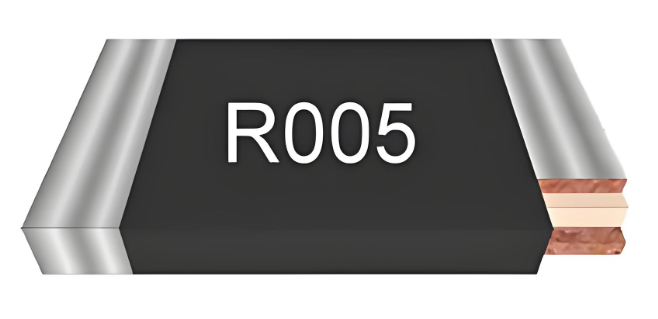
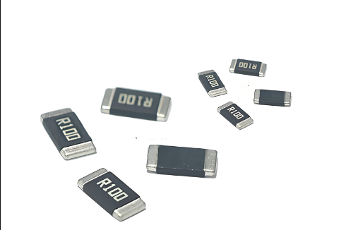
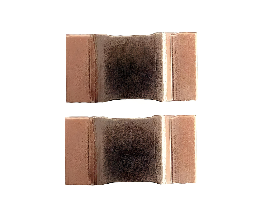
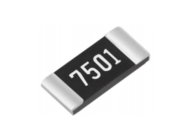
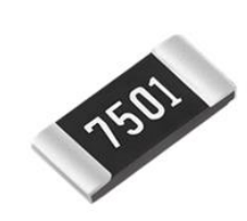
In RF, microwave, and many power-electronics front-ends, a resistor must behave like a pure resistance across the operating band. High Frequency Non-Inductive Resistors are designed and manufactured to minimize parasitic inductance (L) and capacitance (C), preserving intended impedance, reducing insertion loss, and preventing resonance. Choosing the wrong part (for example, a standard wire-wound resistor) often introduces large reactive impedance at GHz, degrading performance.
Key Datasheet Parameters to Check
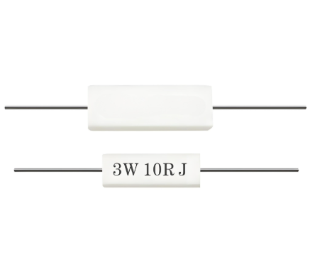
DC resistance & tolerance — nominal value and percent tolerance.
Parasitic inductance (nH) — the lower, the better for RF use.
Parasitic capacitance (pF) — important for shunt terminations and pads.
Impedance vs frequency or S-parameters — the single most useful datasheet item for RF.
TCR (ppm/°C) — thermal stability for precision and power electronics.
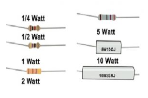
Power rating & thermal resistance — continuous and pulse ratings, and derating curves.
Recommended PCB footprint / mounting — minimizes added parasitics.
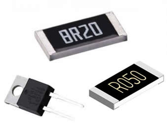
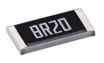
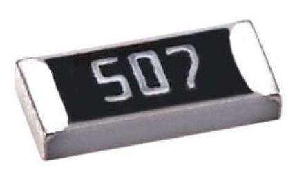
Comparison Table: Common Non-Inductive & RF-Friendly Resistors
Representative ranges shown for quick selection (use as engineering starting points).
| Type | DC Range | Parasitic L (nH) | Parasitic C (pF) | TCR (ppm/°C) | Notes |
|---|---|---|---|---|---|
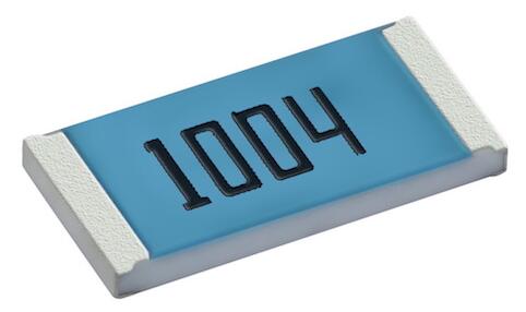
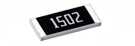
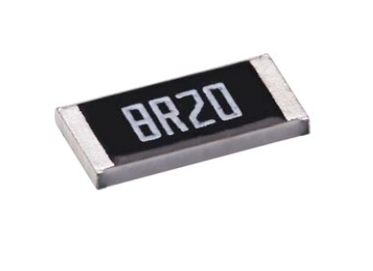
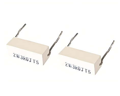
| Thin-film SMD (non-inductive layout) | 0.1 Ω – 1 MΩ | 0.02 – 0.3 | 0.005 – 0.2 | 5 – 50 | Best general RF choice for GHz bands |
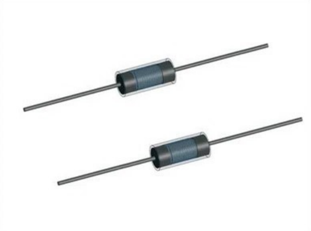
| Metal-foil precision | 0.01 Ω – 10 kΩ | 0.01 – 0.2 | 0.002 – 0.1 | 0.5 – 10 | Highest stability and lowest L |
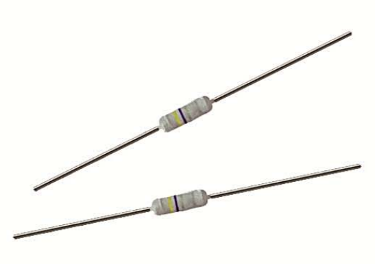
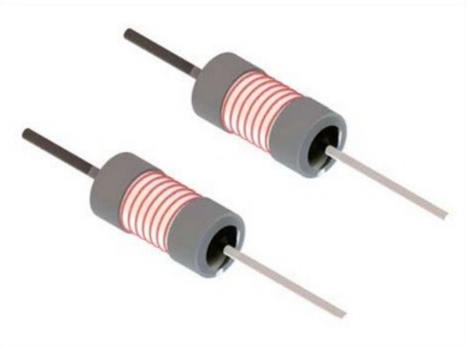
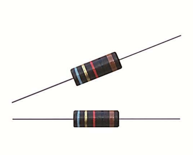
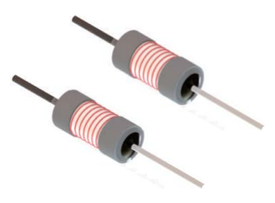
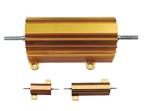
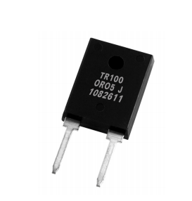
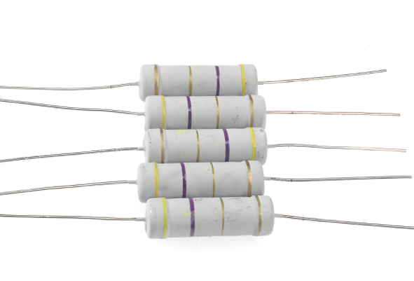
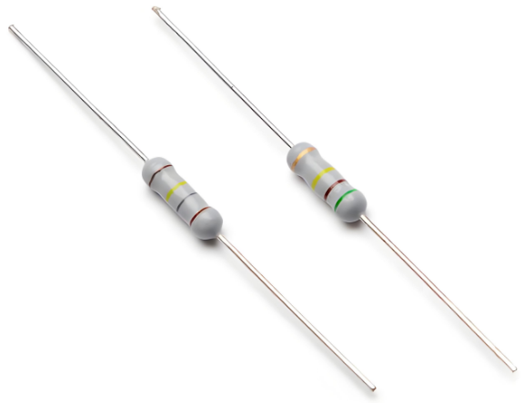
| Non-inductive wire-wound (bifilar) | 0.01 Ω – 1 kΩ | 0.1 – 1.0 | 0.02 – 0.5 | 20 – 200 | Good power but limited to lower GHz |
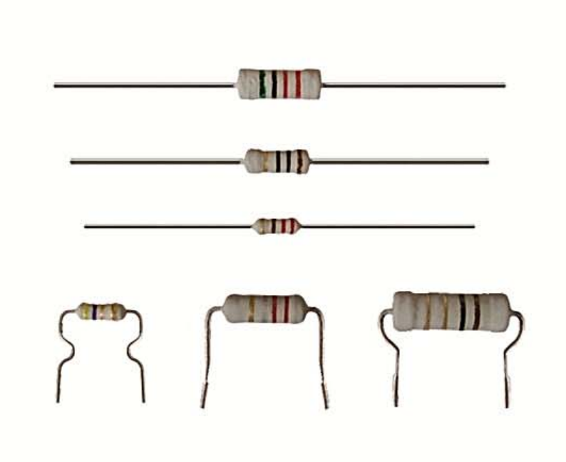
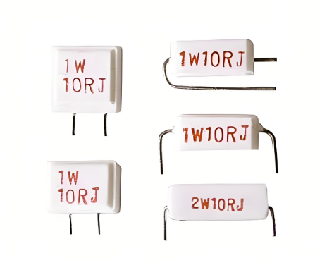
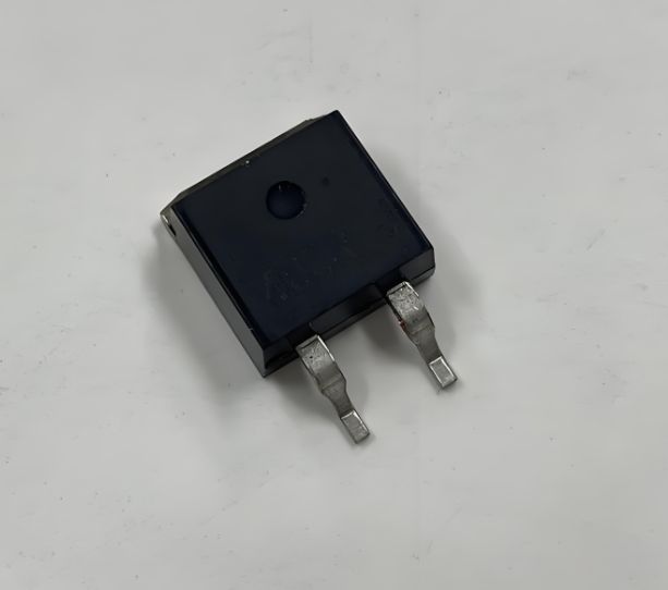
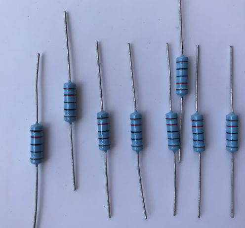
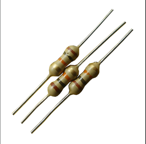
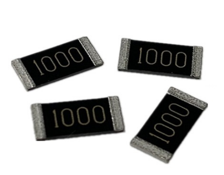
| Thick-film SMD (standard) | 1 Ω – 10 MΩ | 0.3 – 2.0 | 0.05 – 0.8 | 100 – 500 | Low cost, higher parasitics — avoid for mmWave |
Reactance Examples — Why Small L Kills Performance
Inductive reactance XL = 2πfL. The table below shows XL for small parasitic inductances at several common RF and mmWave frequencies. Use this to judge how a tiny L may dominate intended resistance.
| Parasitic L (nH) | 2.4 GHz (Ω) | 28 GHz (Ω) | 60 GHz (Ω) |
|---|---|---|---|
| 0.02 | 0.30 | 3.50 | 7.50 |
| 0.10 | 1.51 | 17.59 | 37.70 |
| 0.50 | 7.54 | 87.96 | 188.50 |
Interpretation: a resistor with 0.1 nH parasitic inductance presents ~17.6 Ω at 28 GHz — potentially overwhelming a small series resistance and causing severe mismatch. This demonstrates why the phrase high frequency resistor non inductive is essential when sourcing parts for RF, microwave, and power-electronics tasks.
Selection & Application Steps
Define role: series damping, termination, bias bleed, attenuator — each role imposes different constraints.
Set worst-case frequency: design for the highest frequency the circuit will see (e.g., up to 60 GHz for mmWave / 5G FR2).
Choose technology: prefer thin-film or metal-foil non-inductive parts for GHz; reserve wire-wound (bifilar) for lower-frequency high-power needs.
Verify parasitics & S-parameters: only finalize parts that include impedance vs frequency or S-parameter files.
Simulate with parasitics: include L and C in circuit or EM models and sweep the band.
Prototype & measure: measure S11/S21 and insertion loss on the target PCB layout.
Concrete Problem You Will See
Problem: Unexpected Reflection and Loss at 28 GHz
A 1 Ω series damping resistor was used in a 28 GHz front-end. The chosen part lacked parasitic data. The prototype showed several dB of unexpected loss and S11 degradation. Investigation identified parasitic inductance ≈0.5 nH in the resistor, producing ≈88 Ω reactance at 28 GHz — dominating the intended 1 Ω and creating a resonance.
Practical Solution — Step by Step
Replace with true non-inductive part: select a thin-film or metal-foil resistor with parasitic L ≤0.05–0.1 nH.
Use RF-rated attenuator pads or distributed resistive traces: for broadband terminations, use matched pads with known S-parameters.
Optimize layout: shorten traces, minimize via count, use low-inductance ground stitching, and follow vendor footprint recommendations.
Include parasitics in simulation: update models and simulate across the full band to confirm return loss and insertion loss improvements.
Measure and iterate: perform S-parameter measurements with the final resistor in-place; tweak layout or part choice if necessary.
Buying Tips & Datasheet Insights
Prioritize parts that publish impedance vs frequency or S-parameter files for your band.
Ask for parasitic inductance (nH) and capacitance (pF) if not listed.
Request recommended PCB footprint and mounting guidance to minimize added L.
For high-volume or critical systems, request sample parts and test them on your real board before committing to production.
Consider vendors that offer SPICE and S-parameter models to accelerate accurate simulation.
Conclusion
Selecting High Frequency Non-Inductive Resistors is a combination of part technology, datasheet scrutiny, simulation, and measured validation. For RF, microwave, and power-electronics applications — especially in 5G and mmWave designs — minimizing parasitic inductance and verifying frequency behavior is mandatory to achieve intended performance.
FAQ
Q: Can I use a standard thick-film resistor in a 5G mmWave design?
No — standard thick-film resistors typically have higher parasitics and are unsuitable for mmWave. Choose thin-film or metal-foil non-inductive parts and verify S-parameters.
Q: What numeric parasitic L should I target for 28 GHz?
Target parasitic inductance ≤0.05–0.1 nH where possible. Use the reactance table above to confirm that XL remains small relative to your intended resistive value.
Note: This article is an applied selection guide for High Frequency Non-Inductive Resistors for RF, Microwave, and Power Electronics. It intentionally avoids external citations and focuses on practical numeric examples, datasheet checks, and actionable selection steps you can apply immediately.