Title: High Frequency Resistor Selection Guide for RF, Microwave, and 5G Circuits – Design Tips, Datasheet Insights & Buying Advice
Introduction
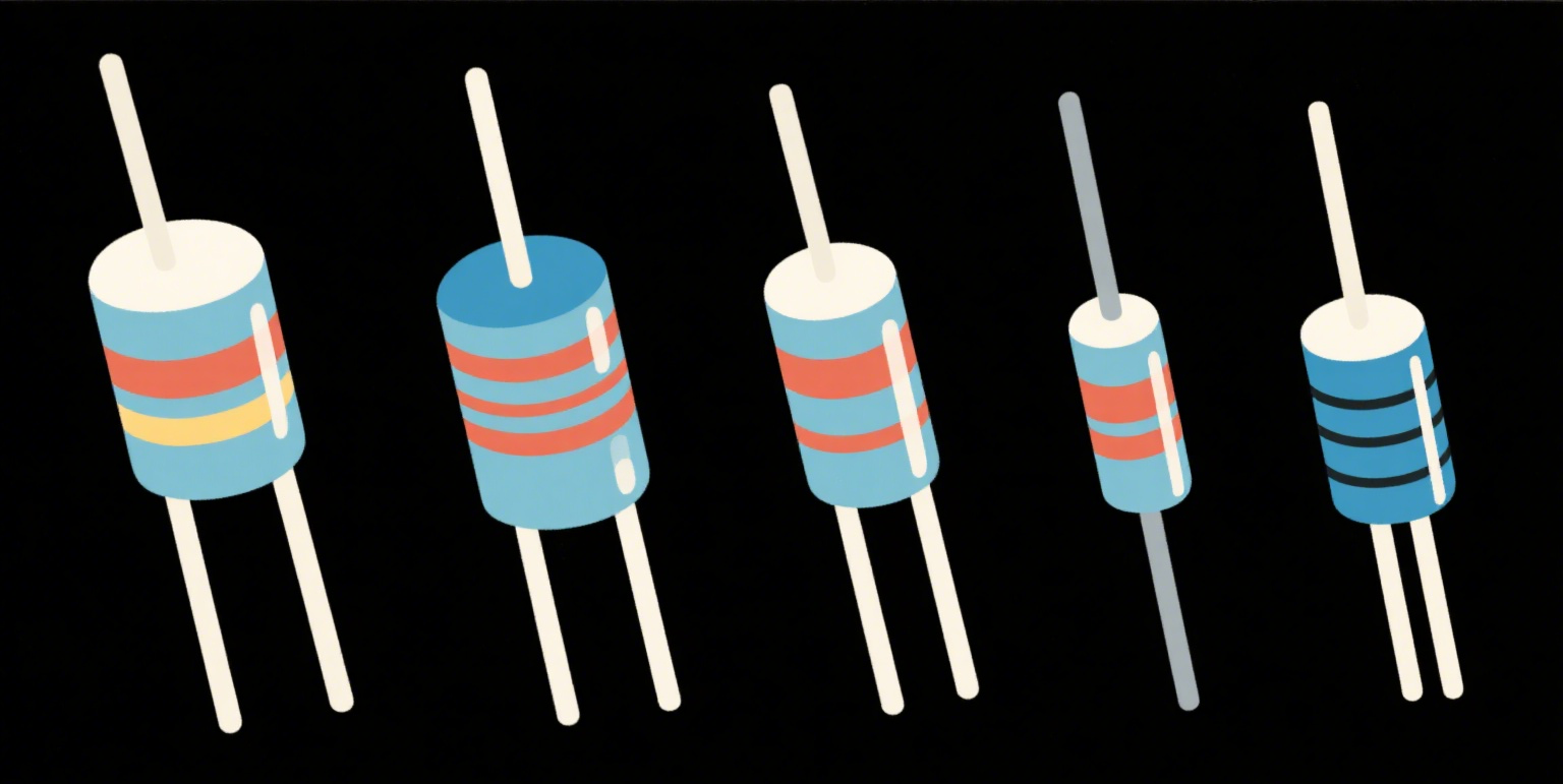
This High Frequency Resistor Selection Guide for RF, Microwave, and 5G Circuits explains how to choose resistors that perform reliably at GHz frequencies. High-frequency systems place different demands on resistors than DC or low-frequency designs: parasitic inductance and capacitance, frequency-dependent impedance, noise, and package-driven effects often dominate. Use this guide to understand the measurable parameters, compare common resistor types with real data, and apply practical design tips and buying advice for high-frequency resistor selection and application.

Table of Contents
Why High-Frequency Resistor Selection Matters
In RF, microwave, and 5G circuits a resistor is rarely a pure real-valued load. Parasitic inductance (L) and capacitance (C) create frequency-dependent impedance. A resistor chosen for its DC value may behave like an inductor, capacitor, or resonant element at high frequency — causing mismatch, loss, unwanted filtering, or oscillation. This high frequency resistor selection guide focuses on how to avoid those pitfalls and achieve predictable performance up to mmWave bands.
Key Datasheet Parameters to Check
DC Resistance & Tolerance — base value and tolerance (%).
Parasitic Inductance (nH) — often listed or measurable; critical at GHz.
Parasitic Capacitance (pF) — important for shunt or termination resistors.
Frequency Response / Impedance vs Frequency — look for plots or S-parameters.
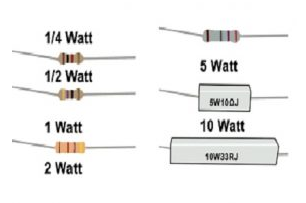
Power Rating & Thermal Resistance — derating at elevated temperature and in RF environment.
Noise / Voltage Coefficient — noise figure contributions in sensitive front ends.
Package and Mounting — leads, pads, and via proximity change parasitics.
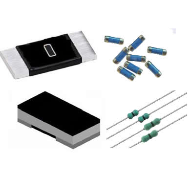
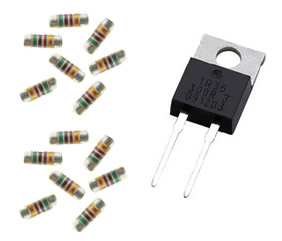
Comparison of Common Resistor Types (with data)
Table below shows typical characteristic ranges you will see on datasheets for resistors used in RF/microwave/5G applications. Values are representative ranges (not citations) useful for quick selection.
| Type | Typical DC Range | Typical Parasitic L (nH) | Typical Parasitic C (pF) | TCR (ppm/°C) | Strengths |
|---|---|---|---|---|---|
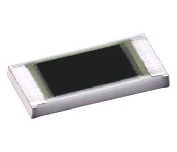
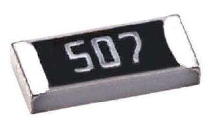
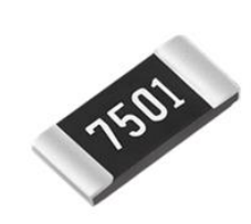
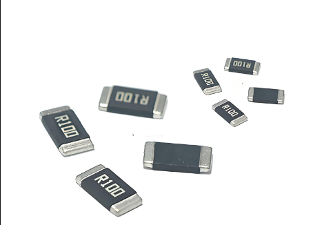
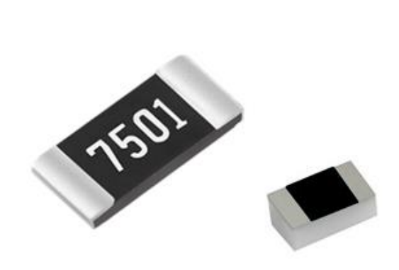
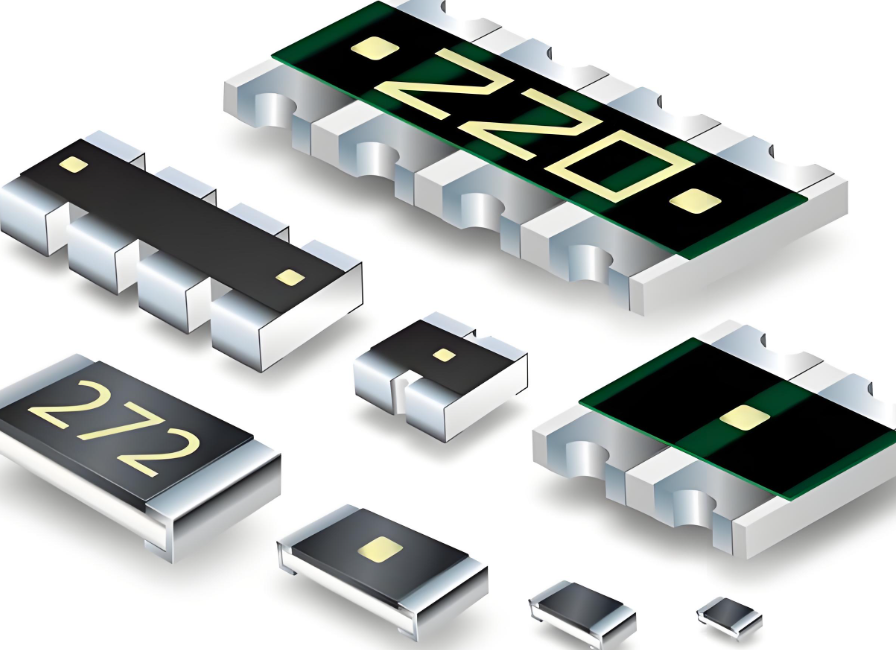
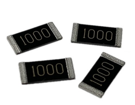
| Thin-film SMD (non-inductive design) | 0.1 Ω – 1 MΩ | 0.05 – 0.3 | 0.01 – 0.2 | 5 – 50 | Low L, stable, good high-freq performance |
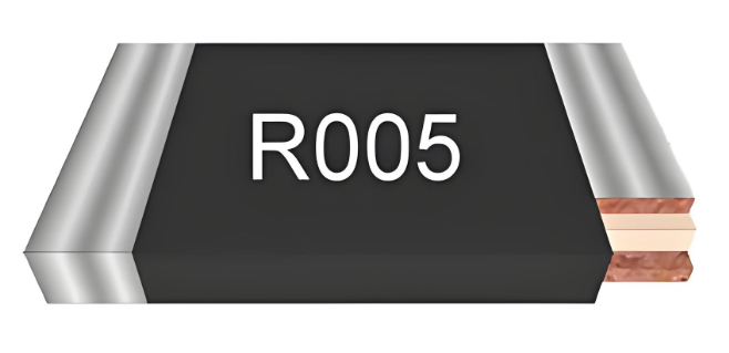
| Metal foil / precision | 0.01 Ω – 10 kΩ | 0.02 – 0.2 | 0.005 – 0.1 | 0.5 – 10 | Highest stability, lowest L, precision |
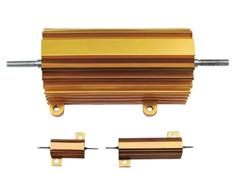
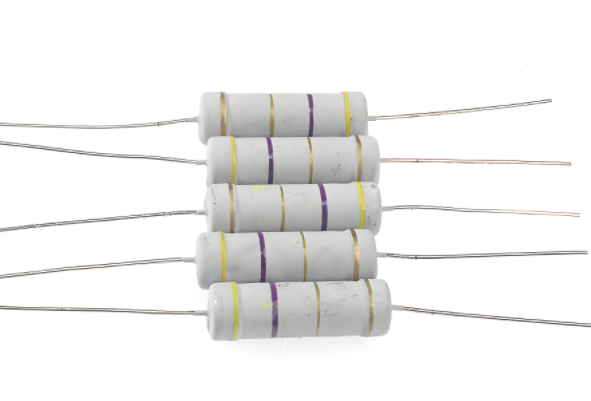
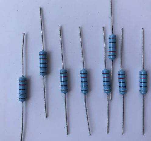
| Wire-wound (standard) | 0.01 Ω – 1 kΩ | 0.8 – 5.0 | 0.1 – 1.0 | 50 – 200 | High power but high L (unsuitable at GHz) |
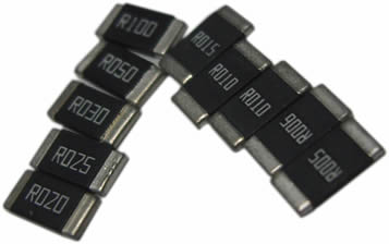
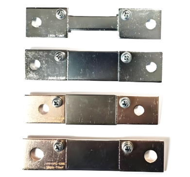
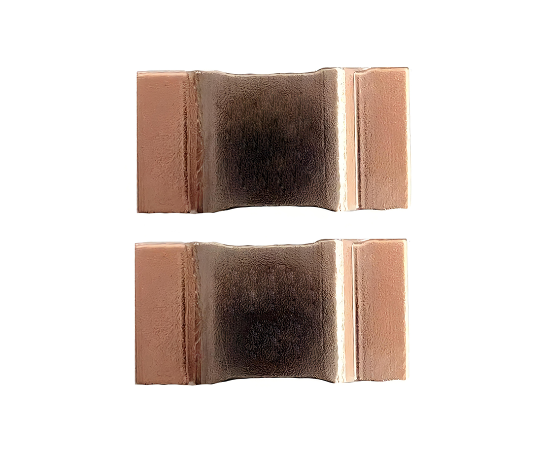
| Manganin / Alloy strip | 0.05 Ω – 10 Ω | 0.2 – 1.0 | 0.05 – 0.5 | 10 – 100 | Good stability and power; moderate L |
| Thick-film SMD | 1 Ω – 10 MΩ | 0.4 – 2.0 | 0.05 – 0.5 | 100 – 500 | Low cost, higher parasitics |
Frequency Impact: Reactance Examples
Even tiny inductances produce significant reactance at RF and mmWave frequencies. The following table shows the inductive reactance XL = 2πfL for a few representative parasitic inductances at commonly used frequencies (2.4 GHz, 28 GHz, 60 GHz). These values show why parasitic L matters when selecting a resistor for RF, microwave, or 5G circuits.
| Parasitic L (nH) | Freq = 2.4 GHz (Ω) | Freq = 28 GHz (Ω) | Freq = 60 GHz (Ω) |
|---|---|---|---|
| 0.10 | 1.51 Ω | 17.59 Ω | 37.70 Ω |
| 0.50 | 7.54 Ω | 87.96 Ω | 188.50 Ω |
| 2.00 | 30.16 Ω | 351.86 Ω | 753.98 Ω |
Takeaway: at mmWave frequencies (28–60 GHz), even 0.1 nH of parasitic inductance can introduce tens of ohms of reactance, completely dominating a low-value resistor intended as a 50 Ω termination or small series resistance. This is why this high frequency resistor selection guide emphasizes low-L parts and careful layout.
Step-by-Step Selection Guide
Set the circuit role: series damping, termination (50 Ω), attenuator, bias network, or current sense. Requirements differ by role.
Choose target impedance or voltage drop: e.g., 50 Ω termination vs. 5 Ω series damping.
Check frequency band: specify worst-case frequency (e.g., up to 60 GHz for mmWave / 5G FR2).
Pick resistor technology: prioritize thin-film, foil, or special non-inductive SMD types for GHz operation; avoid standard wire-wound for RF.
Verify parasitics and S-parameters: prefer parts with published impedance vs frequency or S-parameter files.
Model and simulate: include resistor parasitics in EM or circuit simulation (SPICE + L/C model) before finalizing.
Prototype and measure: measure insertion loss, return loss (S11), and noise in the real board layout.
A Practical Problem You Will See
Problem: Unexpected Impedance and Signal Loss at 28 GHz
A design uses a 1.0 Ω SMD resistor in series as a damping element for a 28 GHz frontend. The resistor datasheet lists only DC value and power rating; no parasitic data is provided. In the first prototype the S11 shows a deep mismatch and the amplifier gain is reduced by several dB. Troubleshooting reveals the chosen resistor has a parasitic inductance ≈0.5 nH, producing ≈88 Ω reactance at 28 GHz — far larger than the 1 Ω intended, producing resonance and reflection.
Solution: Design & Layout Remedies
Follow these corrective steps to resolve the issue and prevent recurrence:
Replace with low-L resistor: switch to a thin-film or foil resistor with parasitic L ≤ 0.1 nH (see comparison table). That reduces reactance at 28 GHz from ≈88 Ω to ≈17.6 Ω.
Use matched attenuator pads or distributed resistive networks: when a pure resistive termination is needed at GHz, use purpose-built RF attenuator networks with data to frequency limits.
Optimize PCB layout: minimize via inductance, keep traces short, use symmetric grounding, and place the resistor at the exact RF node with minimal lead length.
Include parasitics in simulation: model L and C in SPICE or EM solver and sweep across the band to verify response before building.
Measure S-parameters: on the prototype measure S11/S21 with the resistor in place; if needed tweak layout or choose alternative part.
Consider dissipative distributed elements: for very wideband or mmWave applications, resistive films or thin resistive traces (designed as matched terminations) often outperform discrete components.
Buying Advice & Datasheet Insights
When evaluating vendors and parts for RF, microwave, or 5G systems, look for the following items in datasheets and supplier information:
Impedance vs Frequency plot or S-parameter file — this beats seeing only DC specs.
Parasitic L and C listed numerically (nH / pF) or summarized by equivalent circuit.
Tolerance and TCR — small TCR helps stability; specify required ppm/°C.
Maximum frequency rating or recommended use up to a given GHz range.
Package / mounting recommendations — some vendors show recommended PCB footprint to minimize parasitics.
SPICE or S-parameter models — these accelerate accurate simulation and shorten debug cycles.
Samples and small-batch availability — to prototype and measure before volume buy.
Conclusion
This High Frequency Resistor Selection Guide for RF, Microwave, and 5G Circuits stressed that DC specs alone are insufficient for high-frequency use. Check parasitic inductance/capacitance, prefer thin-film/foil/non-inductive parts, simulate with realistic models, and prototype with S-parameter measurements. By combining correct part selection, disciplined PCB layout, and verification testing you avoid common GHz and mmWave pitfalls and achieve predictable high-frequency performance.
FAQ
Q: Can wire-wound resistors be used in RF circuits?
A: Standard wire-wound resistors have high parasitic inductance and are generally unsuitable above low MHz. Only special non-inductive wound designs (bifilar etc.) can be used at RF, and even then verify datasheet parasitics.
Q: How do I know if a resistor will work to 28 GHz or 60 GHz?
Ask for impedance vs frequency data or S-parameters. If the vendor cannot provide them, plan to prototype and measure; otherwise choose parts explicitly rated for those bands (thin-film/foil, low L, low C).
Q: If I need a small series resistor at 5G frequencies, what value should I pick?
Choose the smallest DC value that achieves the intended damping or biasing while keeping the resistor's parasitic reactance small relative to the resistive value across the band. Simulate and measure. For many RF uses, distributed or matched resistive pads are preferable to discrete high-L parts.
Note: This article is a practical, self-contained high frequency resistor selection guide for design engineers working on RF, microwave, and 5G circuits. It avoids external citations and focuses on actionable selection criteria, numeric examples, and design solutions you can apply immediately.