Title: High Current Shunt Resistors for Accurate Current Measurement in EVs, Batteries, and Power Supplies – Selection Guide & Buying Tips
Introduction
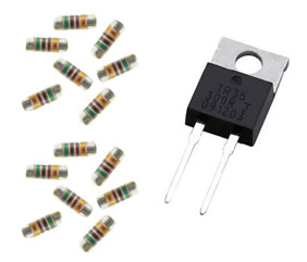
High current shunt resistors are the unsung heroes of precision current measurement in EVs, battery management systems, and industrial power supplies. When chosen and applied correctly, a high current shunt resistor delivers an accurate, repeatable voltage proportional to current with minimal losses and thermal drift. This article is a clear, practical selection guide and buyer's checklist that shows how to size, compare, and apply High Current Shunt Resistors so you get the accuracy you need without creating excess heat or wasted energy.

Table of Contents
Why Use High Current Shunt Resistors?
A shunt resistor converts current into a small, measurable voltage. For applications such as EVs and battery systems, advantages include:
High linearity and direct measurement (no magnetic hysteresis).
Wide dynamic range — from small sensing currents to kilowatt-level systems.
Simple interface to ADCs and differential amplifiers.
How to Calculate Voltage Drop & Power (with data)
Two fundamental formulas:
Voltage drop: V = I × R
Power dissipation: P = I² × R
Below is a worked table that shows voltage drop (V) and power (W) for typical shunt resistances at three representative currents. Values are exact calculations.
| Shunt Resistance (Ω) | Current (A) | Voltage Drop (V) | Voltage Drop (mV) | Power Dissipation (W) |
|---|---|---|---|---|
| 0.0005 (0.5 mΩ) | 100 | 0.05 | 50 | 5 |
| 0.0005 (0.5 mΩ) | 500 | 0.25 | 250 | 125 |
| 0.0005 (0.5 mΩ) | 1000 | 0.5 | 500 | 500 |
| 0.0001 (0.1 mΩ) | 100 | 0.01 | 10 | 1 |
| 0.0001 (0.1 mΩ) | 500 | 0.05 | 50 | 25 |
| 0.0001 (0.1 mΩ) | 1000 | 0.1 | 100 | 100 |
| 0.00001 (0.01 mΩ) | 100 | 0.001 | 1 | 0.1 |
| 0.00001 (0.01 mΩ) | 500 | 0.005 | 5 | 2.5 |
| 0.00001 (0.01 mΩ) | 1000 | 0.01 | 10 | 10 |
Interpretation: lowering resistance reduces the voltage drop (good for efficiency and minimizing ADC input range issues) but requires higher power-handling capability if currents are large.
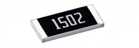
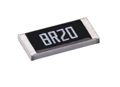
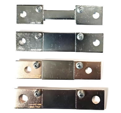
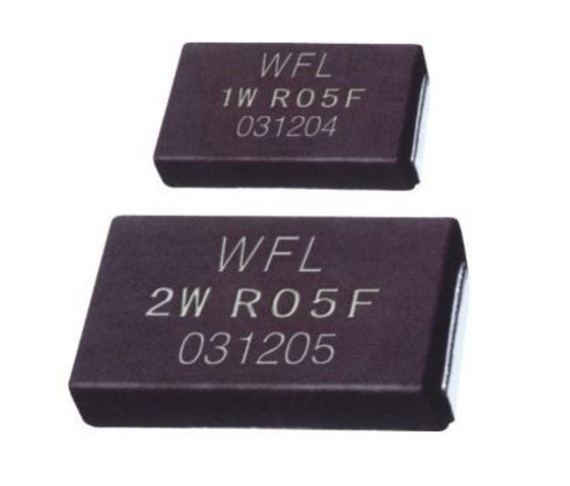
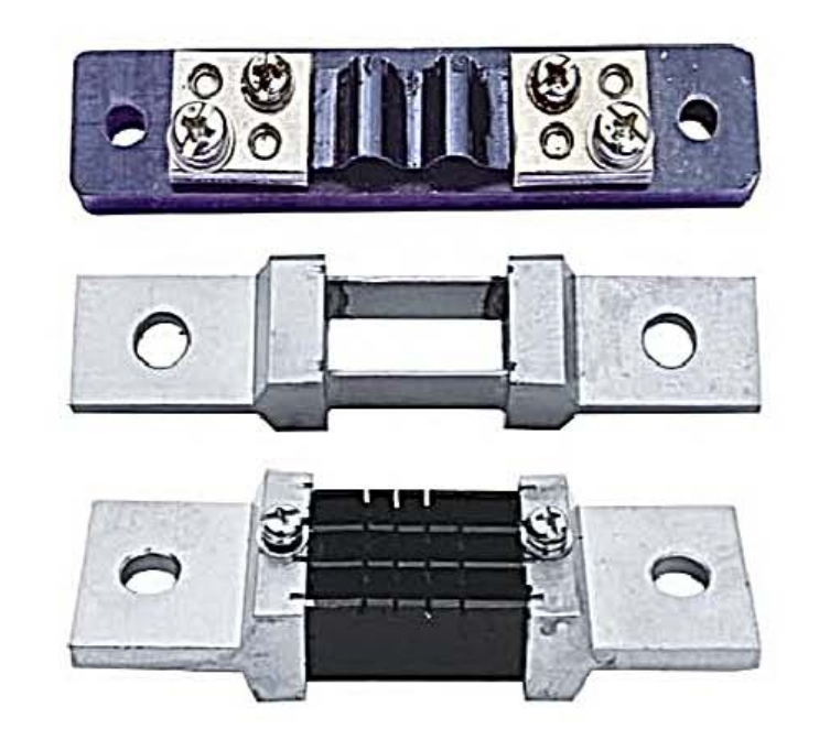
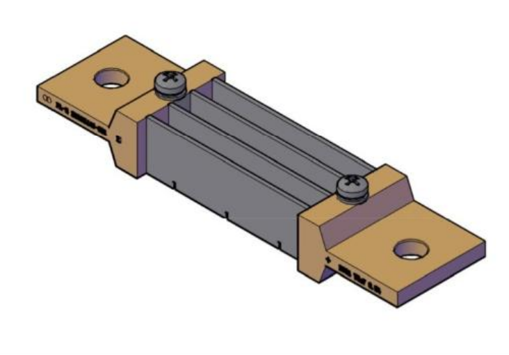
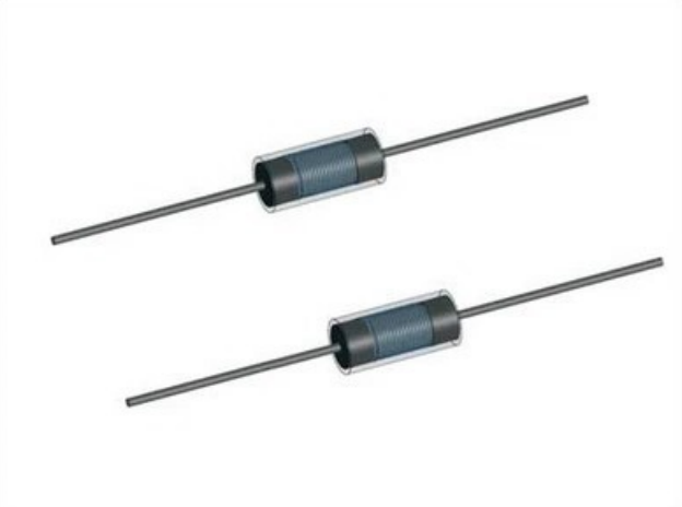
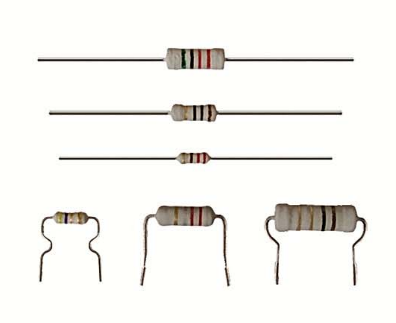
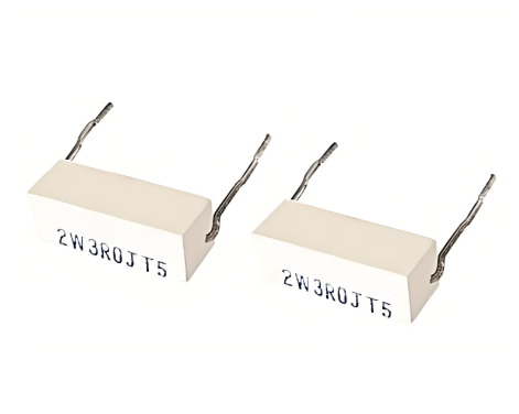
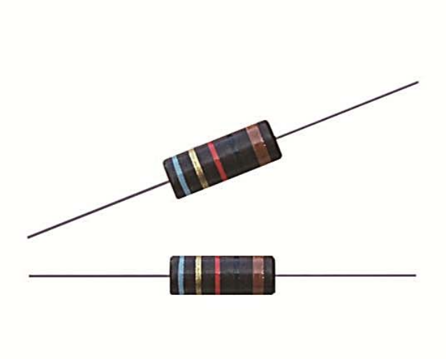
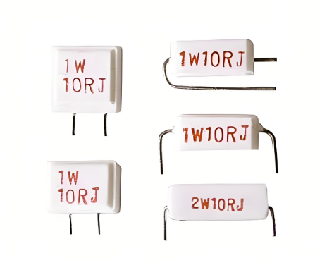
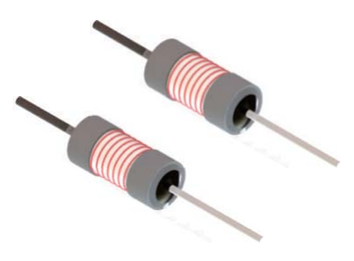
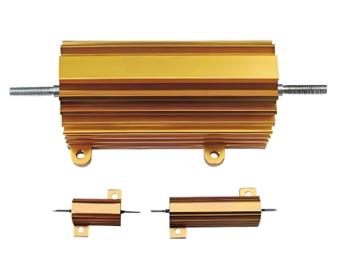
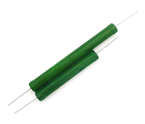
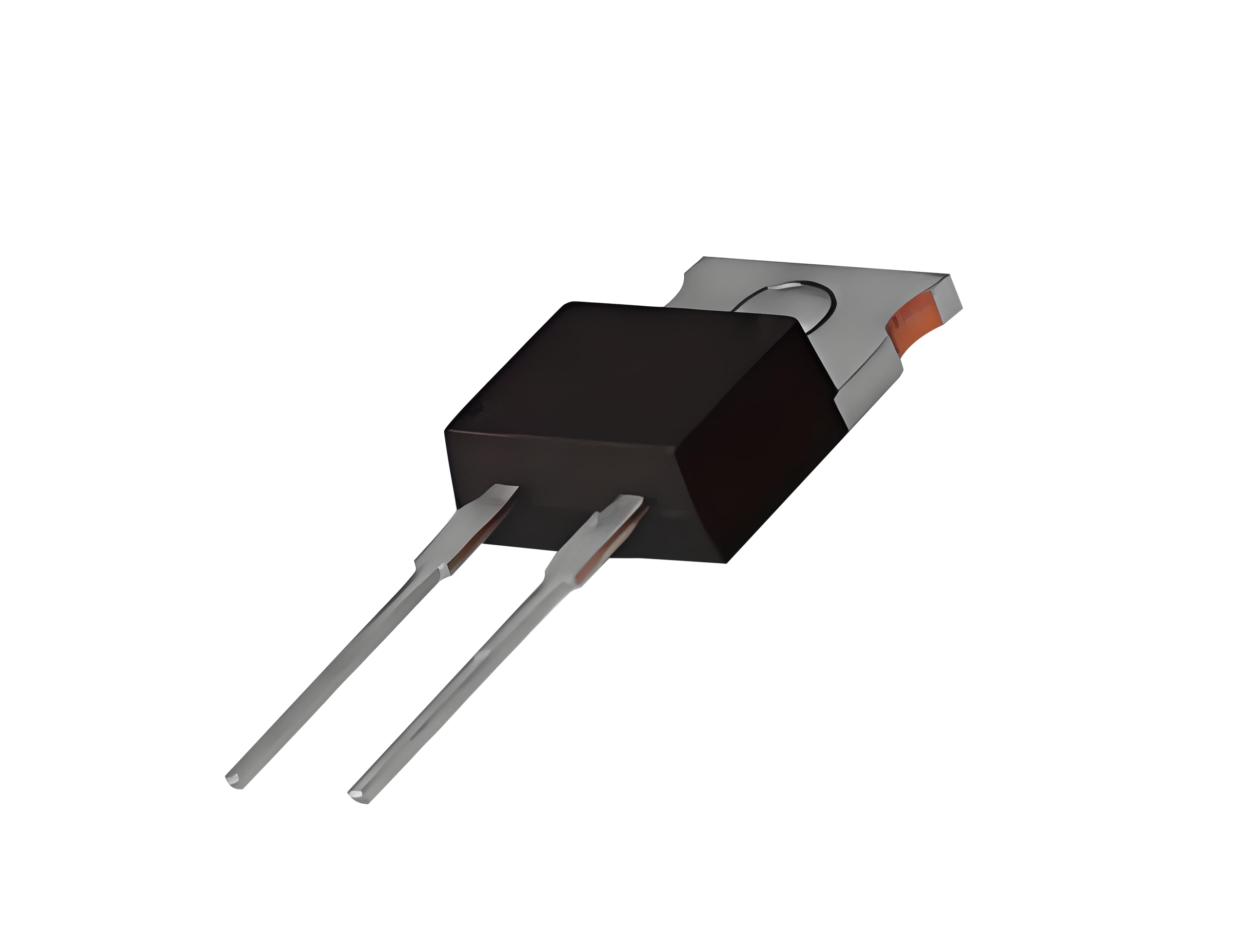
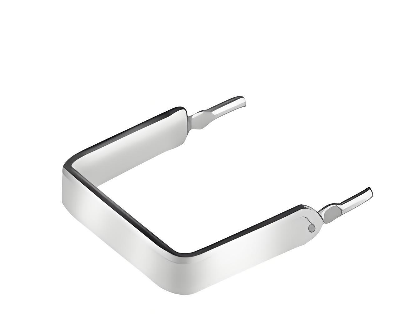
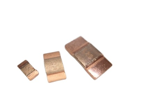
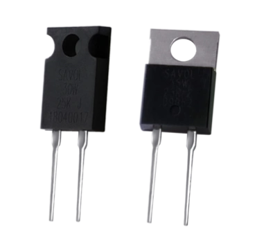
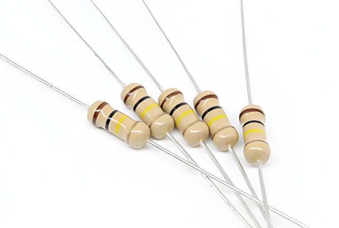
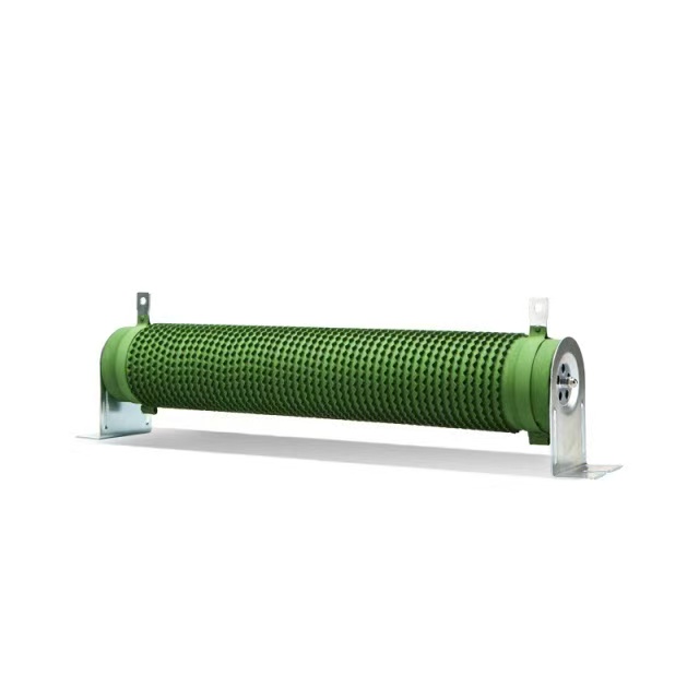
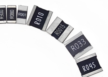
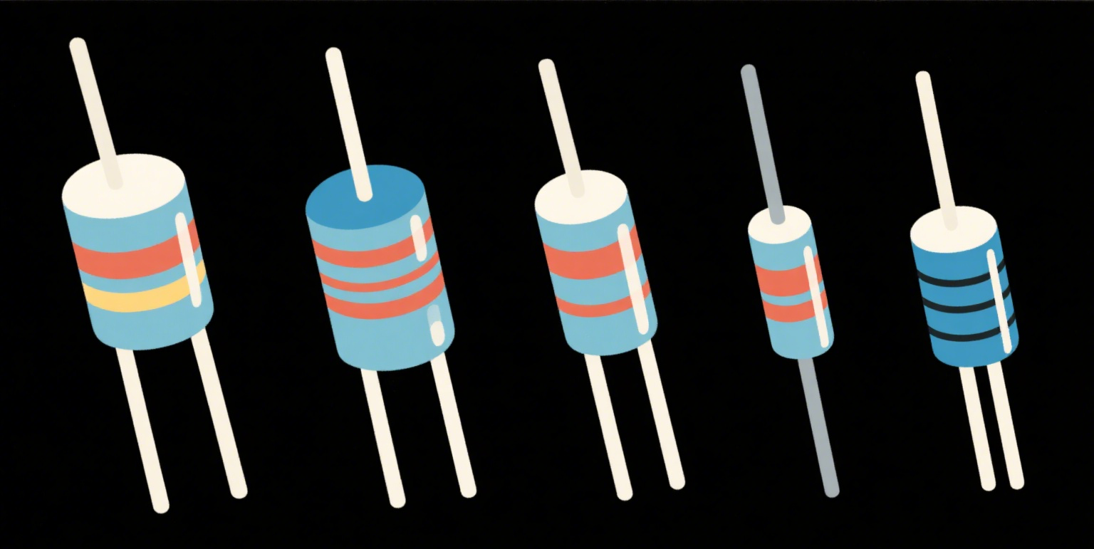
Types of High Current Shunt Resistors — Comparison
| Type | Typical Resistance Range | Accuracy / Stability | Thermal Drift | Common Applications |
|---|---|---|---|---|
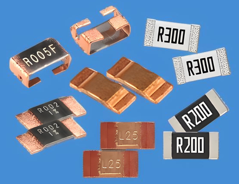
| Foil (precision) | 0.01 mΩ – 1 mΩ | ±0.05% – ±0.5% | Low | Battery management, lab instrumentation |
| Manganin / Alloy | 0.05 mΩ – 5 mΩ | ±0.1% – ±1% | Moderate | Automotive, power converters |
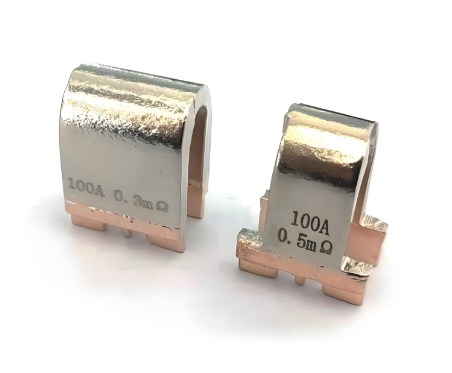
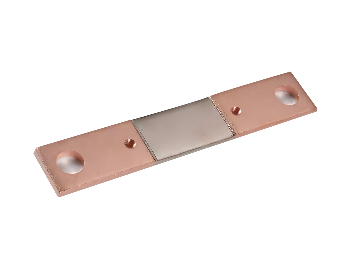
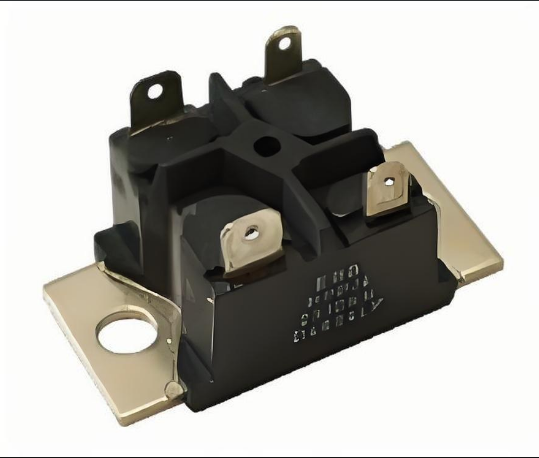
| Busbar / Bolted shunt | ~0.01 mΩ – 0.5 mΩ | ±0.5% – ±2% | Depends on mounting | High current DC distribution, EV traction |
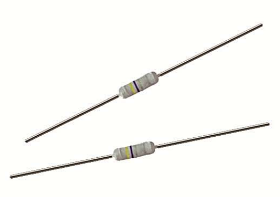
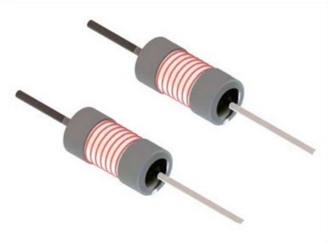
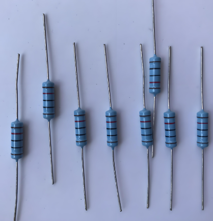
| Wire-wound | 0.1 mΩ – 10 mΩ | ±0.5% – ±5% | Higher | Cost-sensitive power supplies |
Selection Guide: Step-by-Step
Define measurement range and required accuracy.
Example: EV pack current 0–600 A, accuracy target ±1% of reading across the range.
Pick target shunt resistance to set measurable voltage.
Design goal: at maximum current, sensor voltage should be in a convenient range for ADC or amplifier (e.g., 50–200 mV). Use V = I × R to back-calculate R.
Check power dissipation and derate.
Use P = I² × R and select thermal/power rating with margin (≥20–50% safety factor). Consider worst-case continuous current plus environmental temperature.
Account for temperature coefficient (TCR) and stability.
For high-accuracy BMS or EV telemetry, choose alloys or foil shunts with low TCR (ppm/°C) and provide calibration.
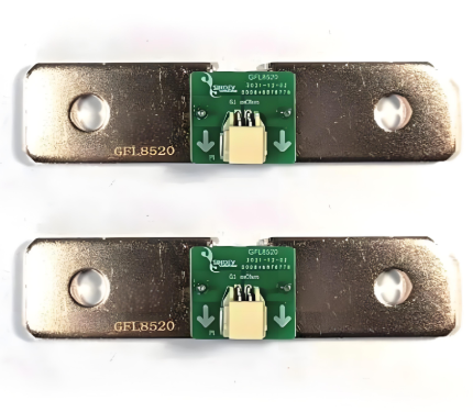
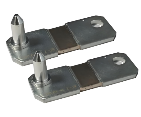
Decide mechanical mounting and Kelvin (4-wire) connection.
Use Kelvin sense terminals to remove lead/contact resistance from your measurement path.
Buying Tips & Checklist
When searching for and purchasing High Current Shunt Resistors, use this checklist:
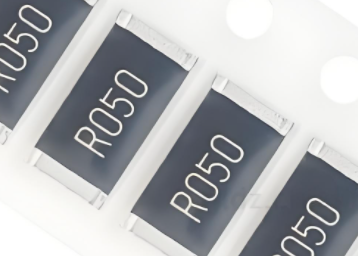
Specified resistance and tolerance (e.g., 0.1 mΩ ±0.5%).
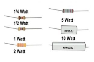
Rated continuous current and rated power dissipation.
Temperature coefficient (TCR) in ppm/°C.
Kelvin-sense terminals availability.
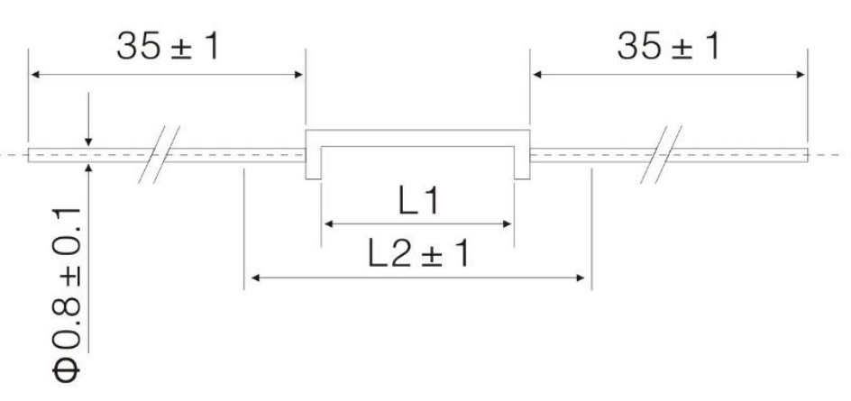
Mechanical mounting style (through-hole, busbar, stud type) and size.
Datasheet that contains thermal derating curves.
Lifecycle and reliability data (cycling, shock, vibration) if for EV use.
A Common Problem — And A Practical Solution
Problem: Excessive Voltage Drop or Overheating in EV/Battery Monitoring
Situation: An EV BMS designer chooses a 0.5 mΩ shunt for 600 A measurement. At peak current the voltage drop is 0.5 mΩ × 600 A = 0.3 V (300 mV), and power dissipation is I²R = 600² × 0.0005 = 180 W. Result: significant energy loss, large heating, and possible derating or thermal runaway if not managed.
Solution: Reduce Resistance, Increase Power Rating, and Improve Sensing
Actionable steps:
Recalculate desired sensing voltage: decide on a smaller target V at max current — e.g., 50–100 mV maximum to limit losses.
Choose a lower resistance: for 600 A and a 100 mV target, R = V / I = 0.1 V / 600 A ≈ 0.0001667 Ω (0.1667 mΩ). Round to a standard value (e.g., 0.15 mΩ or 0.18 mΩ) with appropriate tolerance.
Verify power: P = I² × R. With R = 0.0001667 Ω, P = 360000 × 0.0001667 ≈ 60 W. Then select a shunt rated > 90 W (50% margin) or implement forced cooling/heat sinking.
Use Kelvin connections and low-noise differential amplifier: low voltage drops require good sense wiring to avoid measurement errors from leads and connectors.
Calibrate in-situ: calibrate the measurement chain under controlled current and at expected operating temperatures to compensate for residual offset and TCR.
These steps reduce wasted energy, lower thermal stress, and preserve measurement accuracy—delivering a robust solution for EV, battery, and power-supply applications that rely on High Current Shunt Resistors.
Conclusion
Selecting the right High Current Shunt Resistors requires balancing measurable voltage, power dissipation, mechanical constraints, and accuracy across temperature. Use the simple formulas (V = I×R, P = I²×R), consult the comparison table above, and follow the selection checklist to avoid common pitfalls like excessive voltage drop and overheating. When in doubt, choose lower resistance with adequate power rating, Kelvin sensing, and calibration — and you’ll get accurate current measurement without sacrificing efficiency.
FAQ
Q: When should I pick a busbar shunt vs. a foil shunt?
A: Choose foil (precision) for the tightest accuracy and low TCR. Choose busbar or bolted shunts when mechanical robustness and extreme current-carrying capability are the priority and slightly lower accuracy is acceptable.
Q: Is lower resistance always better?
A: Lower resistance reduces voltage drop and energy loss, but forces the measurement amplifier and ADC to work with smaller voltages — increasing the demand for low-noise amplifiers and higher-resolution ADCs. Balance resistance with your converter/input stage capability.
Q: How important is Kelvin wiring?
A: Essential for any resistance below a few milliohms. Kelvin (4-wire) sensing removes contact and lead resistance from the measurement and dramatically improves accuracy.
Note: This article intentionally avoids external citations and focuses on practical formulas, clear data examples, and a step-by-step selection approach so you can apply the guidance directly when choosing High Current Shunt Resistors for EVs, battery systems, and power supplies.