Introduction: The Heart of the Matter in 5G Design
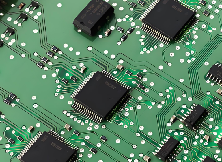
The relentless drive for faster data rates, lower latency, and higher network density in 5G technology pushes every component on a PCB to its performance limits. Among these, resistors, often considered simple passive components, become critical high-frequency actors. The choice between Thin Film and Thick Film resistor technology is no longer a simple cost decision; it's a fundamental engineering trade-off that directly impacts signal integrity, power efficiency, and the overall success of your 5G PCB design for applications like mmWave antennas, power amplifiers, and phase array systems. This article cuts through the speculation to provide a data-driven comparison, helping you answer the pivotal question: which technology is truly best for your specific application?


Technology Basics: How They Are Made
Understanding the fundamental manufacturing difference is key to understanding their performance.
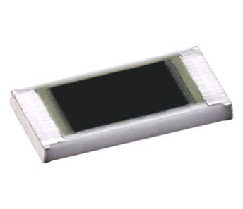
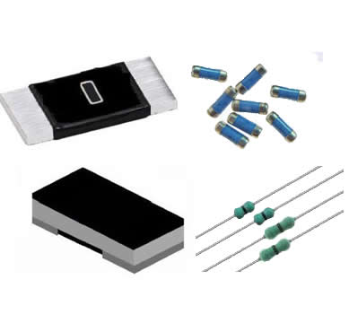
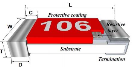
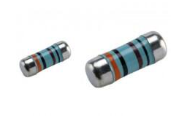
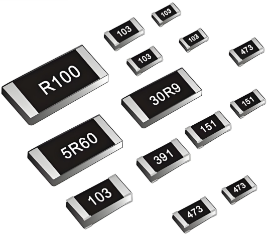
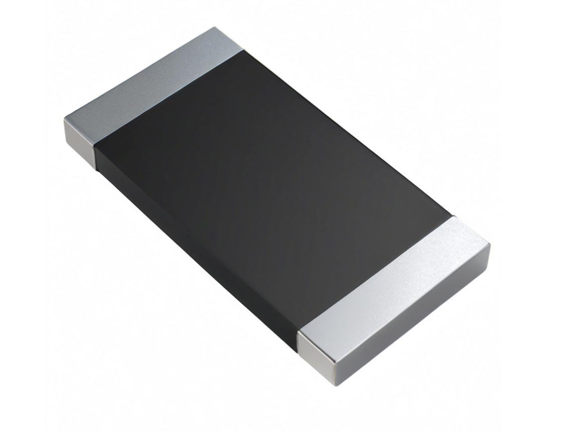
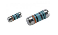
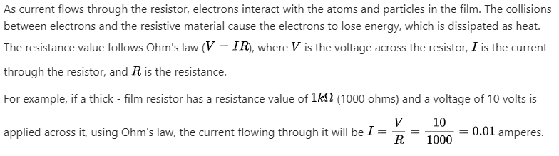
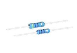
Thin Film Resistors are created by vaporizing a resistive material (like Nichrome or Tantalum Nitride) and depositing it as a very thin layer (typically under 0.1 micrometers) on a ceramic substrate. This fine process allows for extremely precise control over the resistor's value and characteristics. The pattern is typically defined using photolithography, similar to semiconductor manufacturing.
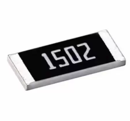
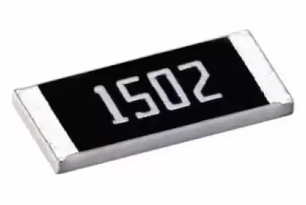
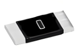
Thick Film Resistors are made by screening a paste—a viscous mixture of glass frit (a powdered glass), conductive metals (like Ruthenium Oxide), and organic binders—onto a ceramic substrate. This layer is much thicker (typically 10-50 micrometers). The substrate is then fired at high temperatures to burn off the organics and fuse the glass and metal into a permanent resistive layer.
Head-to-Head: A Data-Driven Comparison
The following table summarizes the key performance differentiators that are critical for high-frequency applications in 5G.
| Parameter | Thin Film Resistor | Thick Film Resistor | Impact on 5G Performance |
|---|---|---|---|
| Tolerance | ±0.01% to ±1% | ±1% to ±5% | Critical for precision RF matching networks and amplifier biasing. |
| TCR (Temperature Coefficient of Resistance) | ±5 to ±25 ppm/°C | ±50 to ±300 ppm/°C | Low TCR ensures stable performance under thermal stress in 5G power amplifiers. |
| Parasitic Inductance (ESL) | Very Low (0.1-0.5 nH) | Low to Moderate (0.5-2 nH) | Lower ESL preserves impedance matching at mmWave frequencies, reducing signal reflection. |
| Noise | Very Low (< -35 dB) | Moderate (-10 to -35 dB) | Lower current noise minimizes interference in sensitive receiver paths. |
| High-Frequency Response | Excellent into GHz+ range | Good up to several GHz | Thin film maintains resistive behavior closer to its self-resonant frequency. |
| Cost | Higher | Significantly Lower | Drives use-case decision; thick film is preferred for non-critical paths. |
The Core Problem: Parasitic Effects at High Frequency
In a 5G circuit, especially one operating at mmWave frequencies (e.g., 28 GHz, 39 GHz), a resistor is not just a resistor. It acts as a complex network of parasitic inductance (ESL) and parasitic capacitance (ESC).
The Problem Statement: As frequency increases, these parasitics cause the component's impedance to deviate significantly from its ideal DC resistance value. This leads to increased signal reflection, power loss, and phase shifts, which can cripple the performance of a phased array antenna or destabilize a power amplifier. The inherently rougher, granular structure of thick film resistors exacerbates these parasitic effects at higher frequencies compared to the smooth, uniform structure of thin film.
Choosing the Right Resistor: A Solution Framework for 5G Designs
The solution is to match the resistor technology to the specific function within your 5G PCB design. Here is a clear framework to guide your selection process for high-frequency components:
Choose Thin Film Resistors For:
RF Signal Paths: Where precise impedance matching and minimal loss are paramount (e.g., in filters, matching networks).
mmWave Antenna Feed Networks: Where ultra-low ESL is non-negotiable to maintain beamforming accuracy.
Precision Amplifier Biasing: Where low TCR ensures stable operating point over temperature variations.
High-Speed ADC/DAC Reference Circuits: Where low noise is critical for signal accuracy.
Choose Thick Film Resistors For:
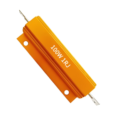
DC/DC Power Converter Snubbers: Where cost and power handling are more critical than high-frequency precision.
Pull-Up/Pull-Down Resistors: For digital control lines where frequency and tolerance are not primary concerns.
Low-Frequency Decoupling/Filtering: In power rails or sub-6 GHz circuits where performance is still adequate.
Cost-Sensitive Consumer 5G Devices: Where balancing BOM cost with acceptable performance is key.
Conclusion: Matching Technology to Application
There is no universal "best" high-frequency resistor technology. The decision between thin film vs. thick film is a calculated compromise between performance and cost. For the core, high-speed heart of your 5G application—where every fraction of a dB of loss and every degree of phase shift matters—thin film resistors are the undisputed champion, offering the superior high-frequency response, stability, and precision required. However, for less critical functions on the same board, thick film resistors provide a reliable and cost-effective solution, enabling you to optimize your overall BOM cost for 5G infrastructure without sacrificing performance where it counts most. By applying this strategic framework, you can make an informed component selection that ensures your design meets its stringent performance targets.