Introduction
Zero ohm jumper resistors are among the most misunderstood components in PCB design. Despite their name, these tiny workhorses play critical roles in circuit board manufacturing, testing, and modification. This guide will explain how zero ohm jumper resistors work in PCB design, why engineers use them instead of simple wire bridges, and how to properly implement them in your projects. We'll also address common problems like current limitations and provide practical solutions for optimal circuit performance.

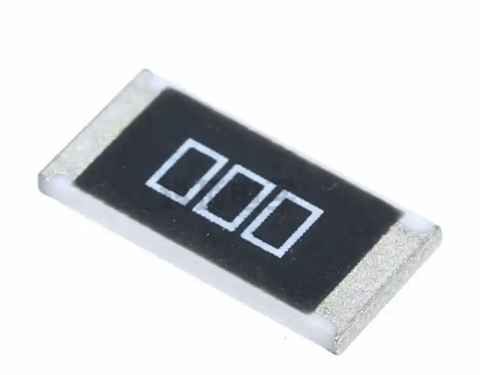
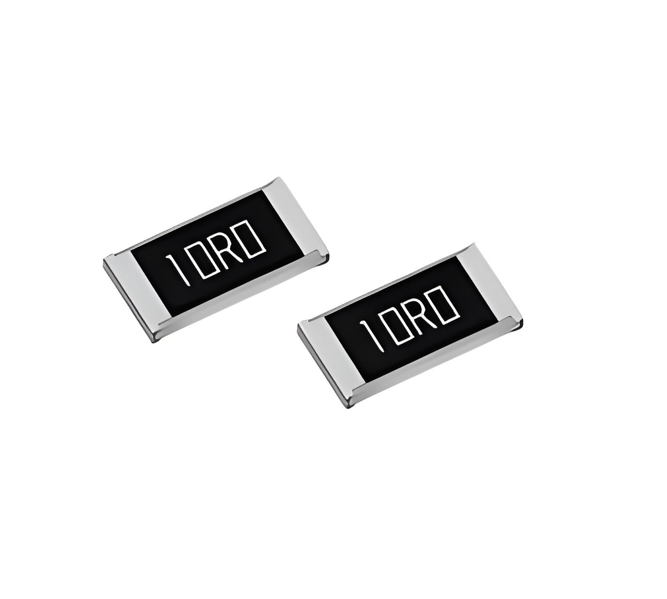
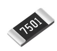
What Is a Zero Ohm Jumper Resistor?
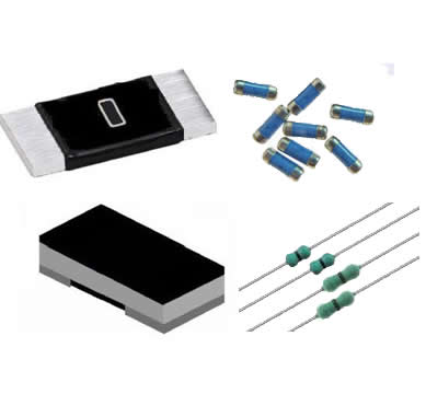
A zero ohm jumper resistor is a specialized component that measures approximately 0Ω resistance, functioning essentially as a wire bridge. However, these components offer advantages that simple wire connections cannot match:
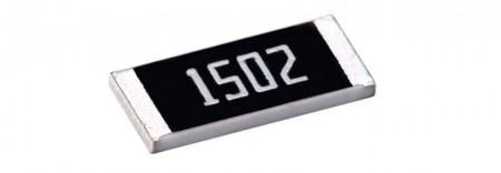
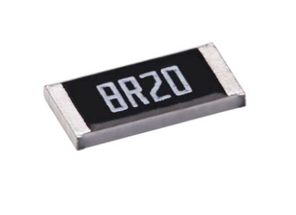
Standardized package sizes matching other SMD resistors
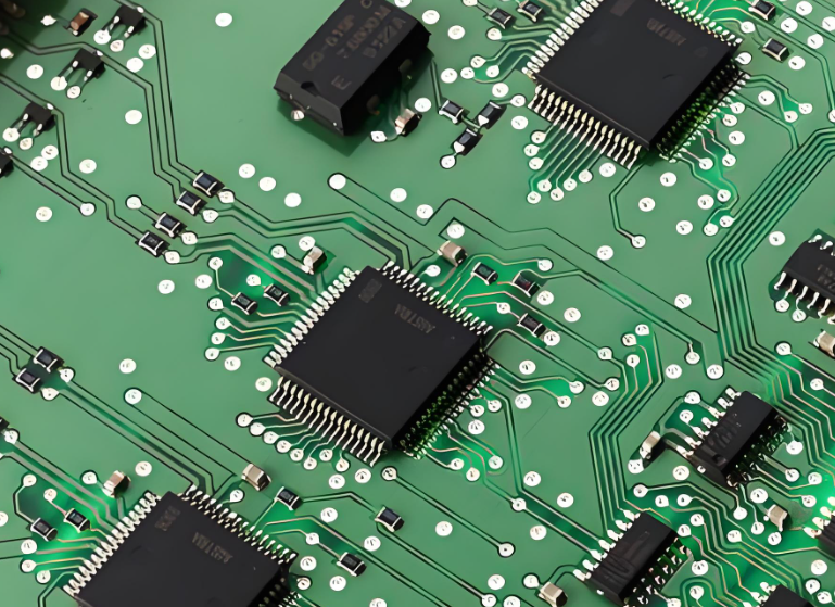
Compatibility with automated PCB assembly machines
Ability to be placed and soldered like regular components
Option to later remove or replace the connection if needed
The Real Purpose of Zero Ohm Resistors in PCBs
While they function as bridges, zero ohm resistors in PCB design serve several important purposes:
| Application | Benefit | Typical Use Case |
|---|---|---|
| Circuit Board Testing | Allows isolating sections of circuitry for diagnostics | Debugging power supply issues |
| Design Flexibility | Enables multiple circuit configurations with same PCB | Hardware version control |
| Automated Assembly | Can be placed by pick-and-place machines | High-volume production |
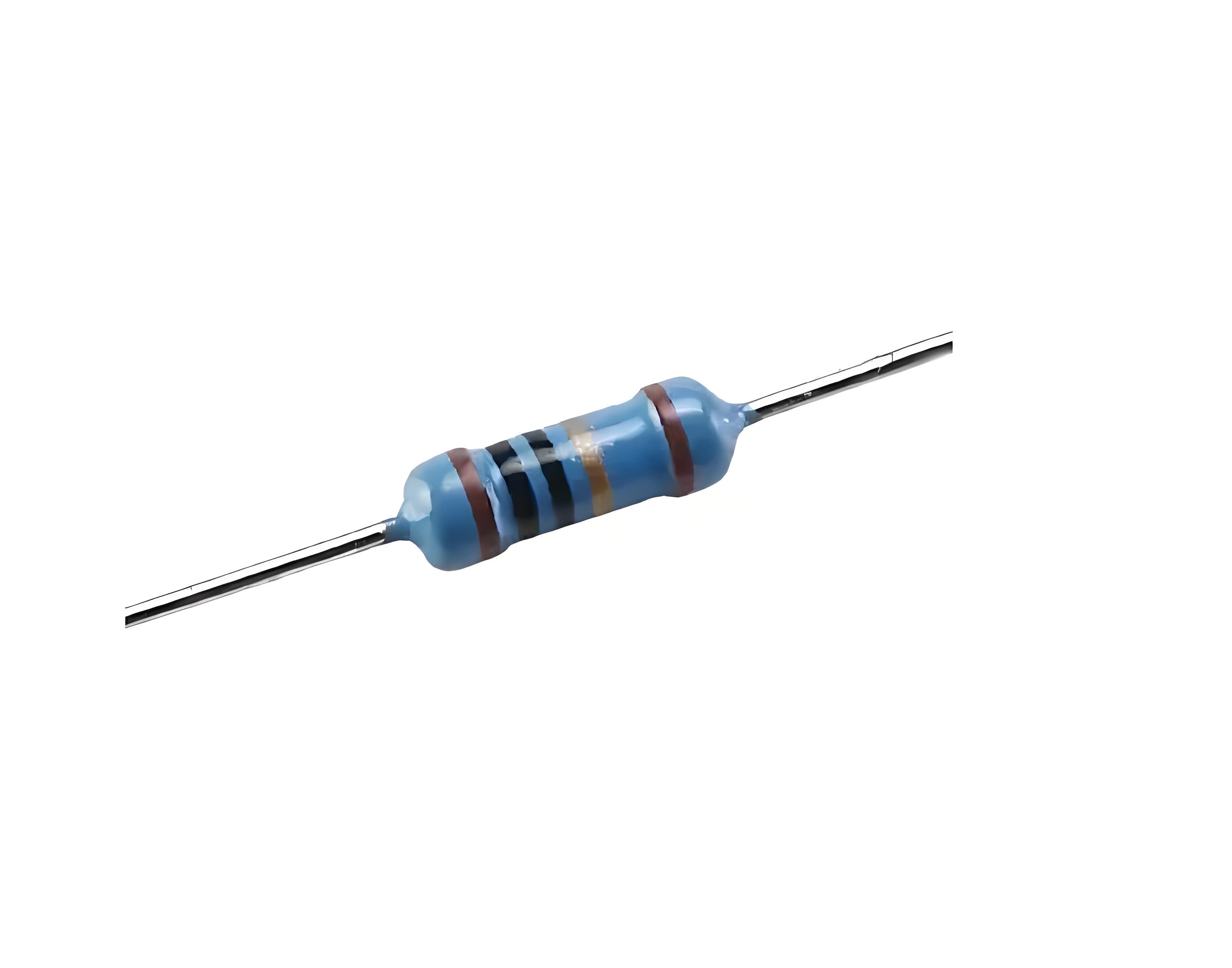
Zero Ohm Resistor vs. Wire Bridge: Key Differences
Many designers wonder why use a zero ohm resistor instead of a wire. Here's the breakdown:
| Feature | Zero Ohm Resistor | Wire Bridge |
|---|---|---|
| Assembly Compatibility | ✔ Works with SMD assembly lines | ✖ Requires manual placement |
| Current Rating | Precisely specified (typically 1-2A) | Depends on wire gauge |
| Design Changes | Easy to remove/replace | Difficult to modify |
| Cost | Slightly higher per unit | Lower, but higher labor cost |
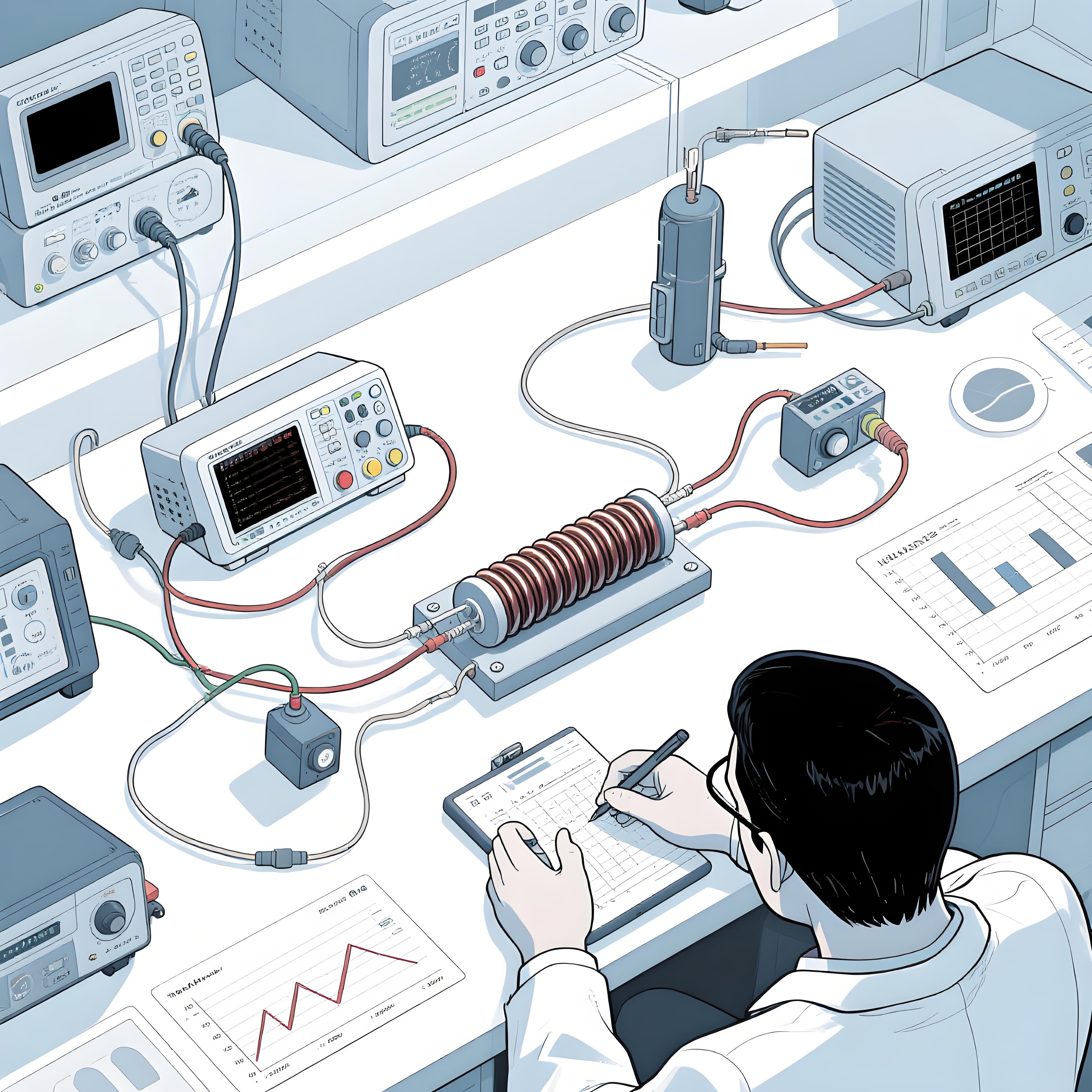
Common Problem: Overheating in High-Current Applications
A frequent issue when using zero ohm jumpers in power circuits is unexpected overheating. Many designers assume "zero ohm" means unlimited current capacity, leading to these failure modes:
Resistor overheating and desoldering itself
PCB trace damage near the jumper
Intermittent connections under load
This occurs because all zero ohm resistors have specific current limitations based on their size and construction.
Solution: Selecting the Right Zero Ohm Resistor for Your Design
To avoid overheating issues when implementing zero ohm jumpers in your PCB, follow these steps:
Calculate expected current: Measure or estimate maximum current through the jumper
Check resistor ratings: Refer to the zero ohm resistor's current specification
Consider package size: Larger packages handle more current (see table below)
Add margin: Select a jumper rated for at least 150% of your expected current
Thermal management: Ensure proper heat dissipation in high-current paths
Zero Ohm Jumper Resistor Specifications Comparison
| Package | Dimensions (mm) | Max Current | Power Rating | Common Applications |
|---|---|---|---|---|
| 0402 | 1.0 × 0.5 | 0.5A | 1/16W | Low-power signal routing |
| 0603 | 1.6 × 0.8 | 1A | 1/10W | General purpose jumpers |
| 0805 | 2.0 × 1.2 | 2A | 1/8W | Power supply routing |
| 1206 | 3.2 × 1.6 | 3A | 1/4W | High-current applications |
Note: Actual ratings vary by manufacturer - always check datasheets.
Best Practices for Using Zero Ohm Jumpers
To get the most benefit from zero ohm resistors in your PCB layout, follow these professional tips:
Group configuration jumpers together for easy identification and modification
Label clearly in schematics as "0Ω" rather than "JUMPER" to avoid confusion
Use for optional components like LEDs or test points that might need removal
Consider future revisions - place jumpers where design changes might occur
Implement in differential pairs to maintain impedance consistency
For high-reliability PCB designs, always specify jumper resistors from reputable manufacturers with proper current ratings.