Introduction
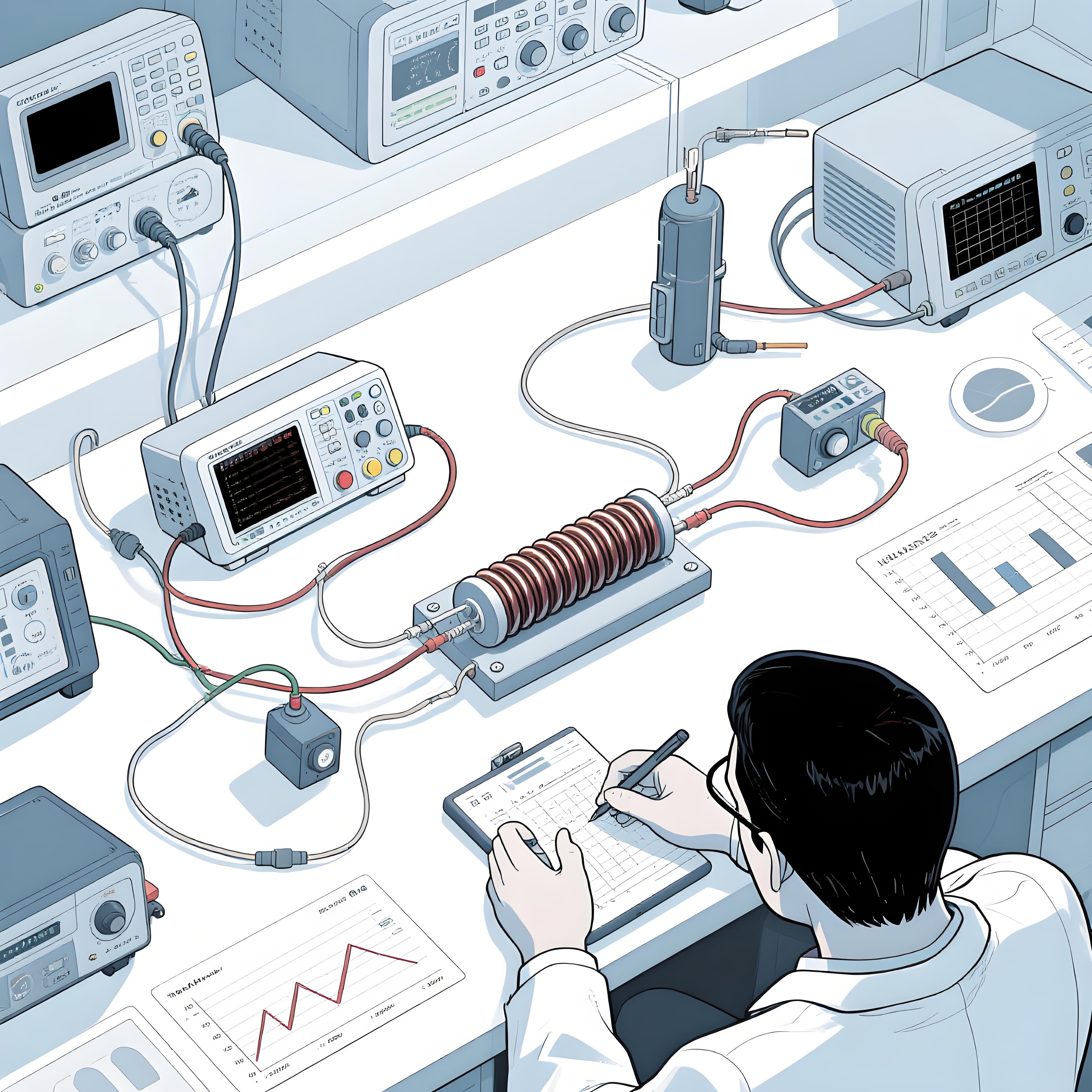
In the realm of electronics, ensuring high voltage protection is paramount for the longevity and reliability of printed circuit boards (PCBs). One effective method to achieve this is through the use of energy absorption resistors embedded directly into the PCB design. These resistors play a crucial role in dissipating excess energy, thereby safeguarding sensitive components from voltage spikes and transient events. This comprehensive guide will delve into the intricacies of integrating energy absorption resistors into PCBs, highlighting their benefits, selection criteria, and practical implementation strategies.

Importance of Energy Absorption Resistors
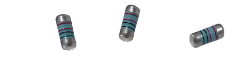
Energy absorption resistors are essential in high voltage applications to protect circuits from transient overvoltages. These overvoltages can be caused by various factors such as inductive loads, switching operations, and electrostatic discharges. Without proper protection, these events can lead to component failure and system downtime.
Table 1 below illustrates the impact of transient overvoltages on different types of electronic components:
| Component Type | Typical Voltage Rating | Impact of Transient Overvoltage |
|---|---|---|
| Microcontrollers | 3.3V - 5V | Permanent damage, data corruption |
| Power MOSFETs | 10V - 100V | Gate oxide breakdown, drain-source short |
| Capacitors | 10V - 500V | Dielectric breakdown, leakage current increase |
| Inductors | Variable | Insulation breakdown, core saturation |
Selection Criteria for Energy Absorption Resistors
Selecting the right energy absorption resistor involves considering several key parameters:
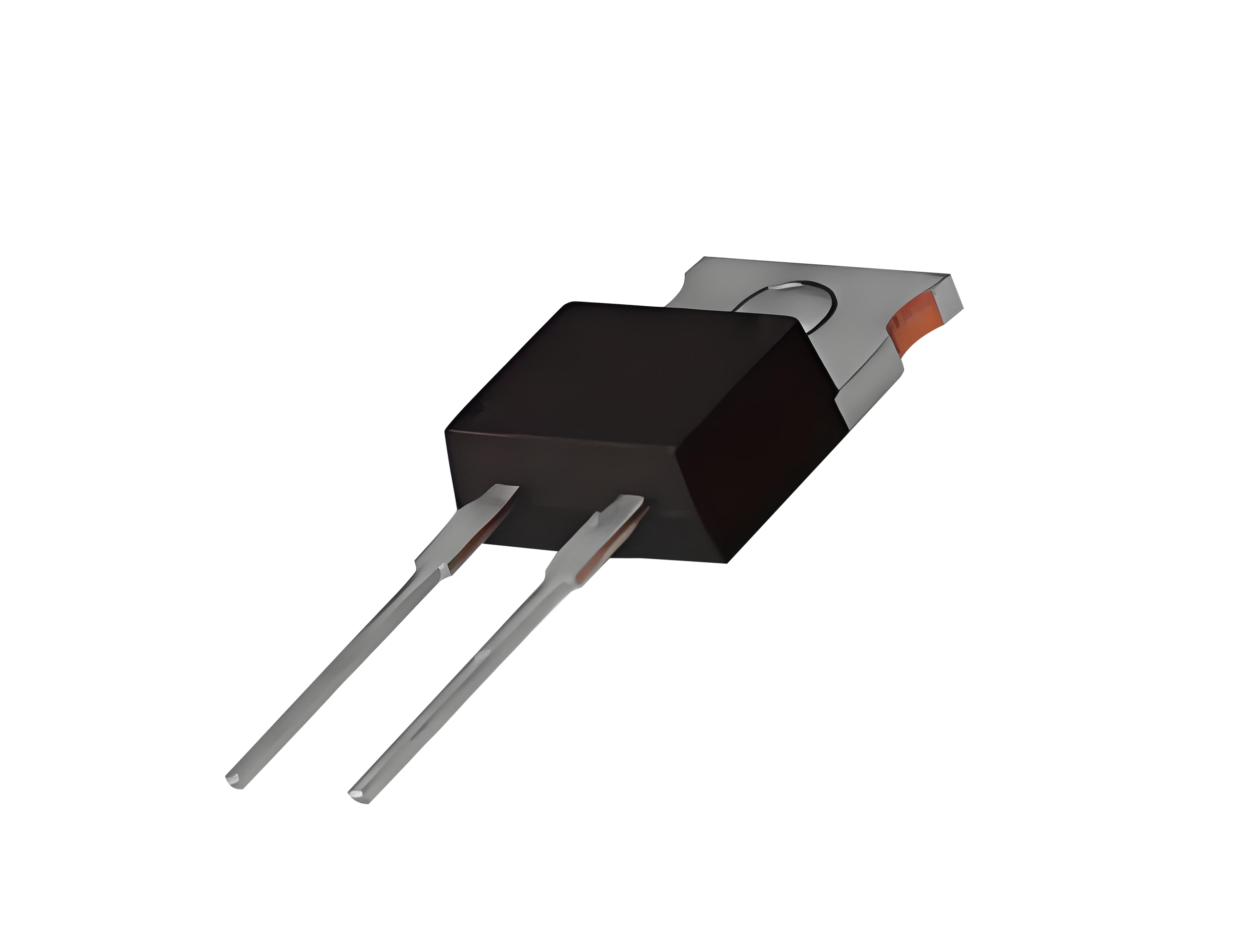
Power Rating: The resistor must be able to dissipate the expected energy pulses without overheating.
Resistance Value: This determines the amount of current that will flow through the resistor during an overvoltage event.
Thermal Stability: The resistor should maintain its resistance value over a wide temperature range.
Physical Size: The resistor must fit within the available space on the PCB.
Table 2 provides a comparison of different resistor types suitable for energy absorption:
| Resistor Type | Power Rating | Resistance Range | Thermal Stability | Physical Size |
|---|---|---|---|---|
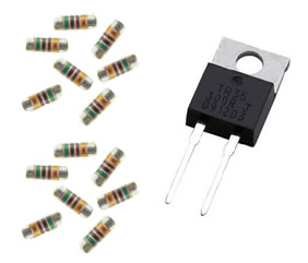
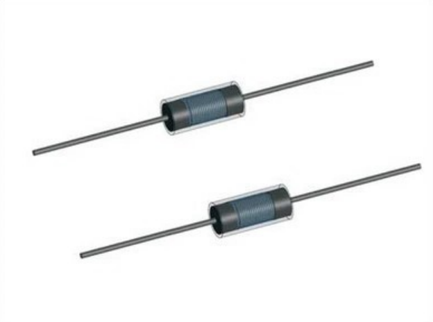
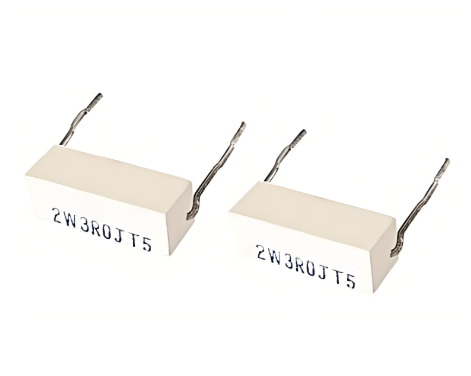
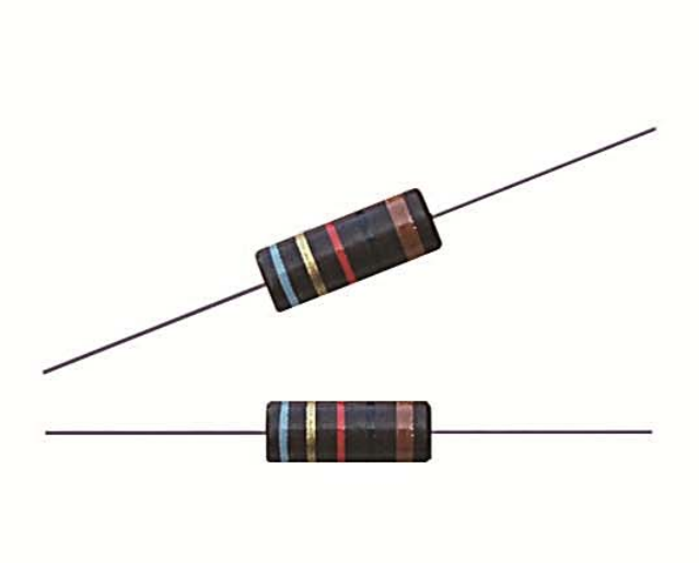
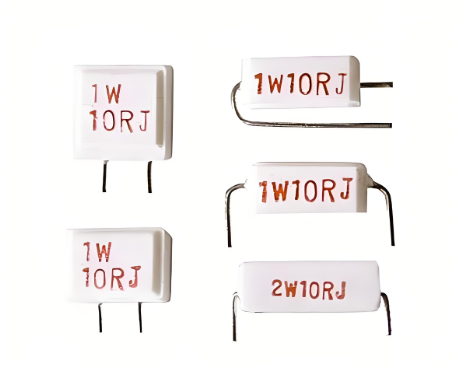
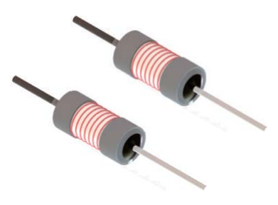
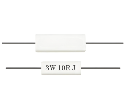
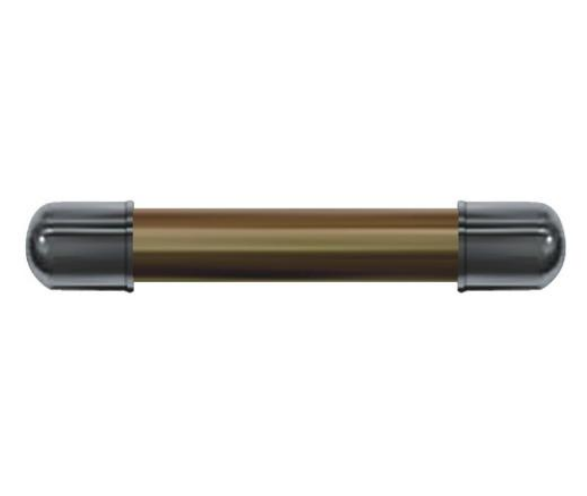
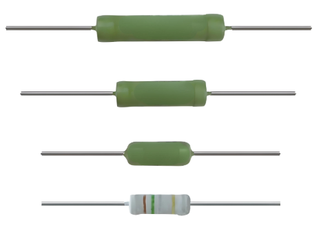
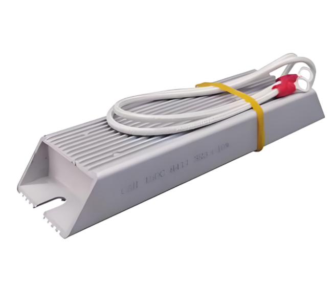
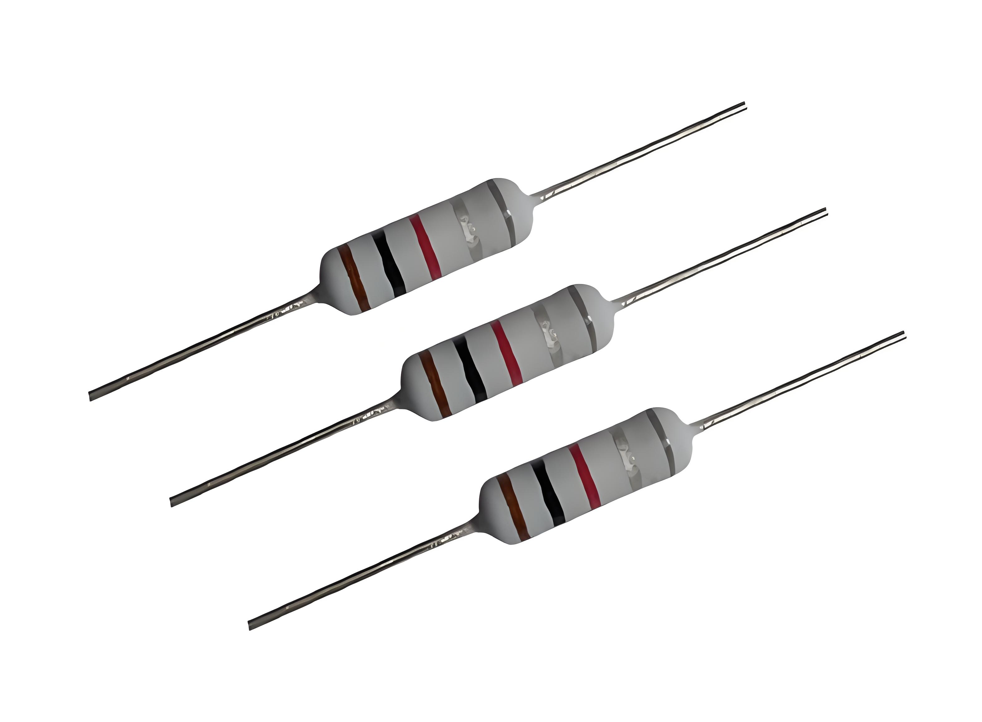
| Wirewound | High (1W - 100W) | 0.1Ω - 100kΩ | Excellent | Medium to Large |
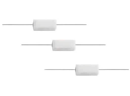
| Film | Medium (0.1W - 10W) | 1Ω - 1MΩ | Good | Small to Medium |
| Thick Film | High (1W - 50W) | 1Ω - 100kΩ | Good | Small to Medium |
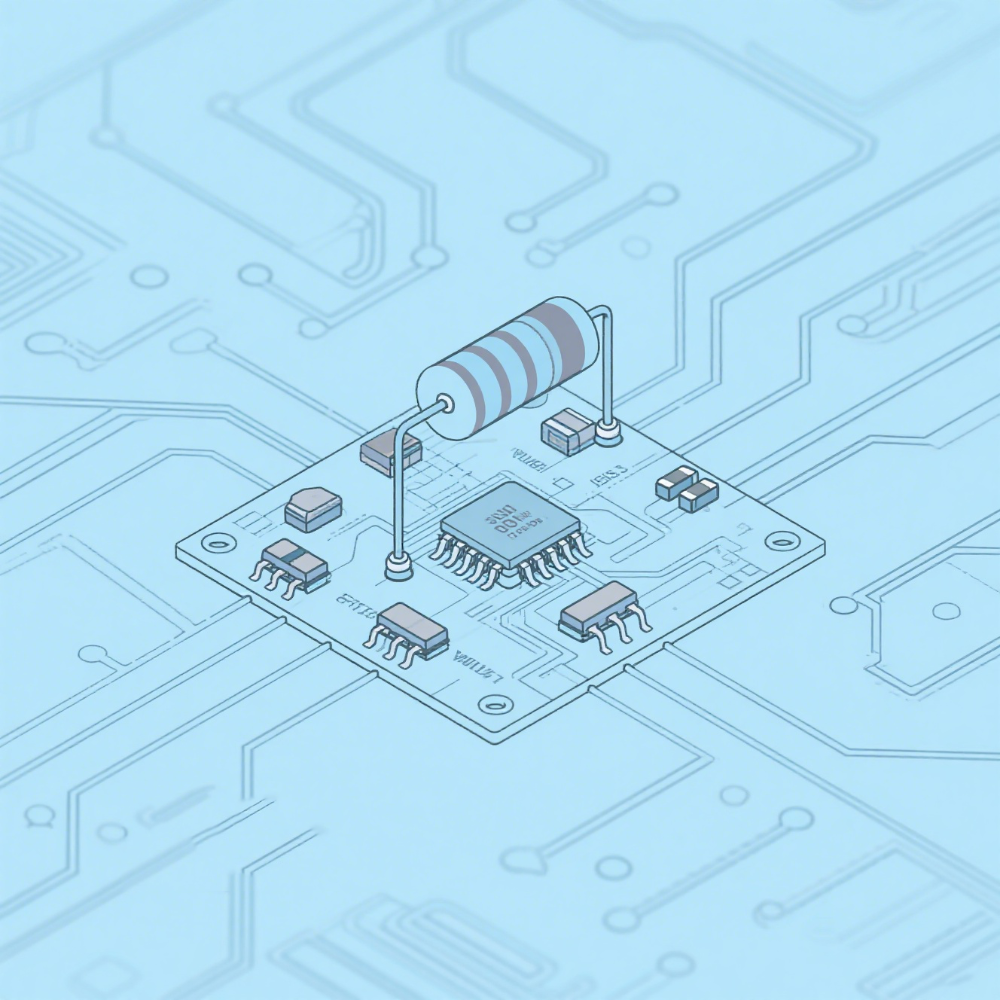
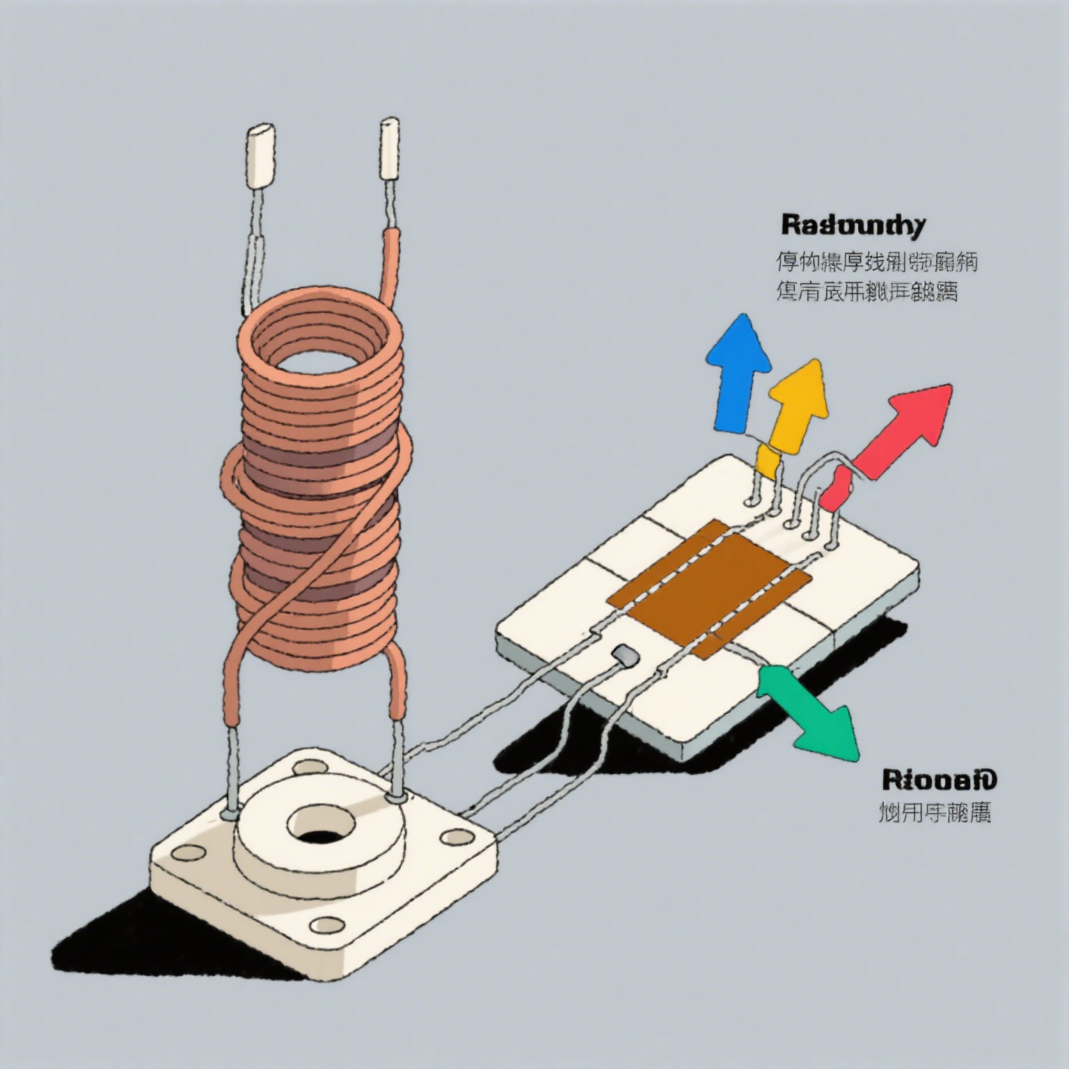
Embedding Techniques
Embedding resistors into the PCB can be achieved through various techniques, each with its own advantages and limitations:
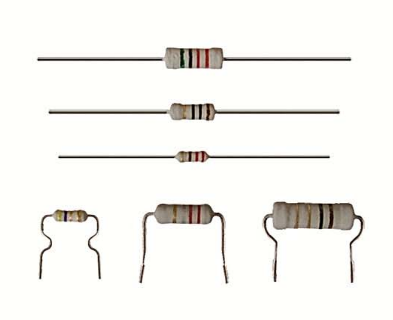
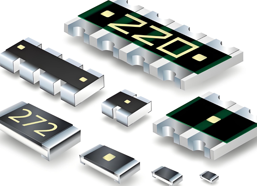
Surface Mount Technology (SMT): Resistors are mounted on the surface of the PCB, allowing for easy inspection and replacement.
Through-Hole Technology (THT): Resistors are inserted into holes drilled in the PCB, providing a more robust mechanical connection.
Embedded Resistor Technology: Resistors are integrated within the PCB layers, reducing the overall footprint and improving thermal performance.
Table 3 compares these embedding techniques:
| Technique | Advantages | Disadvantages |
|---|---|---|
| SMT | Easy to inspect, replace; high component density | Higher thermal resistance |
| THT | Robust mechanical connection | Larger footprint, harder to replace |
| Embedded Resistor | Reduced footprint, improved thermal performance | Difficult to inspect, replace; higher manufacturing cost |
Thermal Management Considerations
Effective thermal management is crucial when embedding energy absorption resistors in PCBs. Excessive heat can lead to resistor degradation and reduced performance. Strategies for thermal management include:
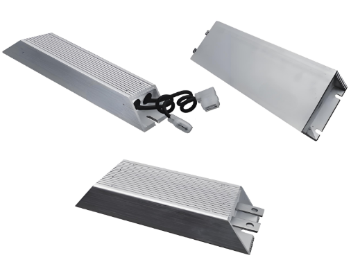
Heat Sinks: Attaching heat sinks to the resistors to dissipate heat more effectively.
Thermal Vias: Using thermal vias to transfer heat away from the resistor and into the PCB substrate.
Thermal Conductive Materials: Employing thermal conductive materials between the resistor and the PCB to enhance heat transfer.
Table 4 provides an overview of thermal management techniques and their effectiveness:
| Technique | Effectiveness | Complexity |
|---|---|---|
| Heat Sinks | High | Medium |
| Thermal Vias | Medium | Low |
| Thermal Conductive Materials | High | Low |
Practical Implementation
Implementing energy absorption resistors in a PCB design involves several steps:
Requirement Analysis: Determine the voltage levels and transient characteristics of the application.
Resistor Selection: Choose a resistor that meets the power rating, resistance value, and thermal stability requirements.
PCB Layout: Design the PCB layout to accommodate the resistor, ensuring proper thermal management and electrical isolation.
Testing and Validation: Conduct tests to verify the resistor's performance under various conditions.
Table 5 outlines a typical implementation process:
| Step | Activity | Considerations |
|---|---|---|
| 1 | Requirement Analysis | Identify voltage levels, transient characteristics |
| 2 | Resistor Selection | Power rating, resistance value, thermal stability |
| 3 | PCB Layout | Thermal management, electrical isolation |
| 4 | Testing and Validation | Performance under various conditions |
Case Study: High Voltage PCB Design
To illustrate the practical application of energy absorption resistors, consider the following case study of a high voltage PCB design for a power supply unit.
Problem Statement: The power supply unit is prone to voltage spikes during switching operations, leading to frequent failures of sensitive components.
Solution: By embedding high power wirewound resistors into the PCB design, the voltage spikes were effectively mitigated. The resistors were selected based on their high power rating (50W) and excellent thermal stability. Thermal vias were used to enhance heat dissipation, and the PCB layout was optimized to ensure proper electrical isolation.